


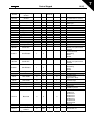
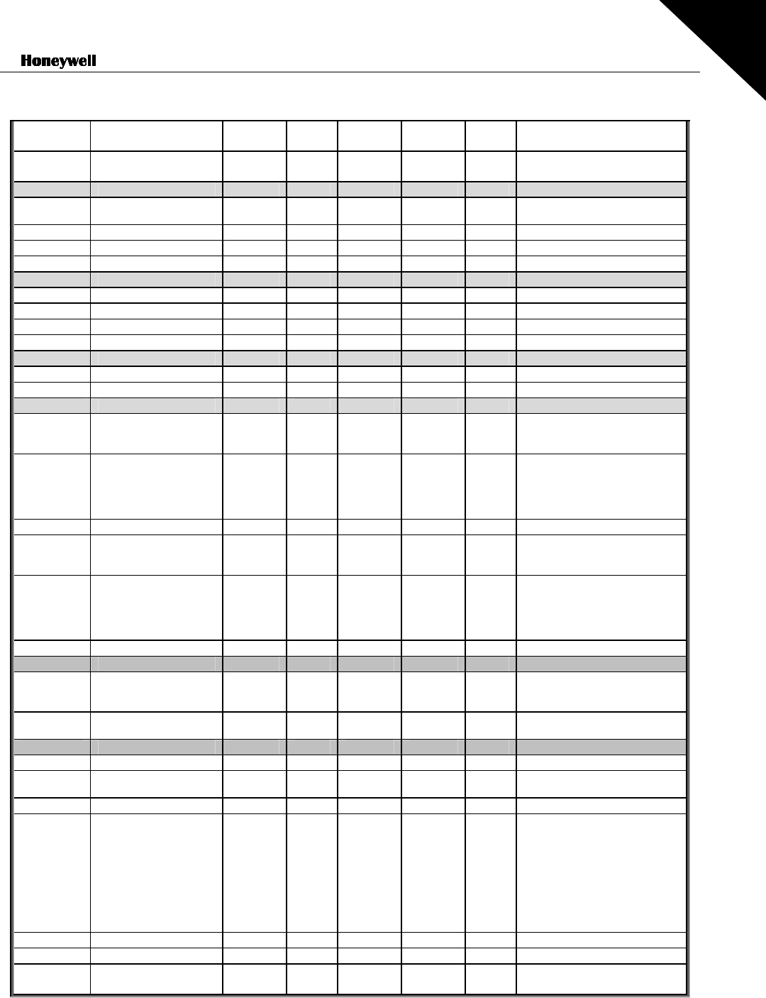
Control Keypad 69(96)
7
T6.8.2.4
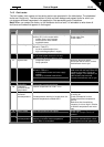
Operating hours trip
counter
hh:mm: ss
P6.8.2.5
Clear operating time
counter
0
= No action
1
= Clear
T6.8.2.3, T6.8.2.4
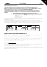
S6.8.3
Software info
I6.8.3.1 Software package
Scroll information with menu
button right
I6.8.3.2 System SW version
I6.8.3.3 Firmware interface
I6.8.3.4 System load %
S6.8.4
Application info
S6.8.4.1 Application
A6.8.4.1.1 Application id
A6.8.4.1.2 Application version
A6.8.4.1.3 Firmware interface
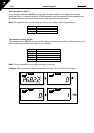
S6.8.5
Hardware info
I6.8.5.2 Unit voltage V
I6.8.5.3 Brake chopper
0
=Not present,
1
=Present
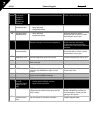
S6.8.6
Options
S6.8.6.1 Slot E OPT-
Note! the submenus are not
showing if no option board is
installed
I6.8.6.1.1 Slot E Status 1 5
1
=Connection lost
2
=Initializing
3
=Run
5
=Fault
I6.8.6.1.2
Slot E Program version
S6.8.6.2 Slot D OPT-
Note! the submenus are not
showing if no option board is
installed
I6.8.6.2.1 Slot D Status 1 5
1
=Connection lost
2
=Initializing
3
=Run
5
=Fault
I6.8.6.2.2
Slot D Program version
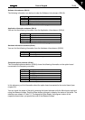
S6.9 AI mode
P6.9.1 AIA1 mode 0 1 0
0
=Voltage input
1
=Current input
(Types MF4 – MF6)
P6.9.2 AIA2 mode 0 1 1
0
=Voltage input
1
=Current input
S6.10 Fieldbus parameters
I6.10.1 Communication status
P6.10.2 Fieldbus protocol 1 1 1
0
=Not used
1
=Modbus protocol
P6.10.3 Slave address 1 255 1 Addresses 1 – 255
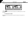
P6.10.4 Baud rate 0 8 5
0
=300 baud
1
=600 baud
2
=1200 baud
3
=2400 baud
4
=4800 baud
5
=9600 baud
6
=19200 baud
7
=38400 baud
8
=57600 baud
P6.10.5 Stop bits 0 1 0
0
=1
1
=2
P6.10.6 Parity type 0 2 0
0
=None
1
=Odd
2
=Even
P6.10.7
Communication
timeout
0 300 s 0
0
=Not used
1
=1 second
2
=2 seconds, etc
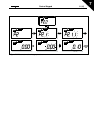
Table 7-5. System menu functions