


Cabling and connections 33(96)
6
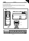
6.1.3 Installation instructions
1
Before starting the installation, check that none of the components of the
frequency converter is live.
2
The NXL frequency converter types MF2 and MF3 shall be installed inside
switchgear, separate cubicle or electrical room because of the protection class
IP20 and the fact that the cable terminals are not protected.
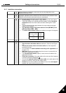
3
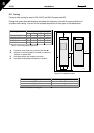
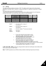
Place the motor cables sufficiently far from other cables:
Avoid placing
the motor cables in long parallel lines with other cables
If the motor cables run in parallel with other cables, note the
minimum
distances
between the motor cables and other cables given in table
below.
The given distances also apply between the motor cables and signal
cables of other systems.
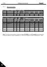
The maximum length of the motor cables is 30 m (MF2-MF3), 50 m
(MF4) and 300 m (MF5 – MF6)
.
The
motor cables should cross
other cables at an angle of 90 degrees.
4
If
cable insulation checks
are needed, see Chapter 6.1.5.
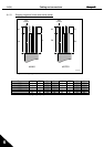
5
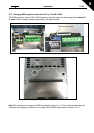
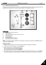
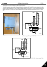
Connect the cables:
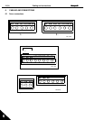
Strip the motor and mains cables
as advised in Table 6-4 and Figure
6-5.
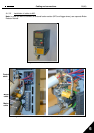
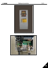
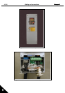
Connect the mains, motor and control cables
into their respective
terminals (see e.g.).
For Information on
cable installation according to UL regulations
see
Chapter 6.1.4.
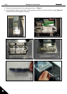
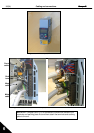
Make sure
that the control cable wires do not come in contact with the
electronic components of the unit.
If an
external brake resistor
(option) is used, connect its cable to the
appropriate terminal.
Check the connection
of the earth cable to the motor and the frequency
converter terminals marked with .
Connect the
separate shield of the motor cable
to the earth plate of the
frequency converter, motor and the supply centre.
Ensure
that the control cables or the cables of the unit are
not trapped
between the frame and the protection plate.
Distance
between cables
[m]
Shielded
cable
[m]
0.3
≤
20
1.0
≤
50