


Commissioning 85(96)
8
8.3
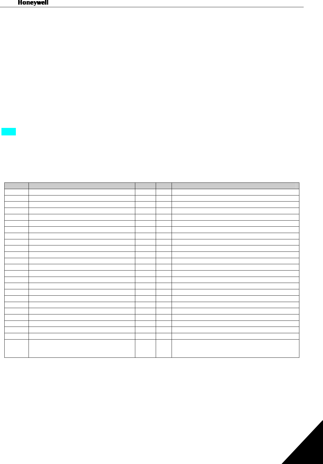
Basic parameters
On the next pages you will find the list of parameters that are essential for the commissioning of the
frequency converter. You will find more details of these and other special parameters in the HVAC and in
the Multi-Control Application manuals.
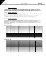
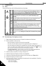
Column explanations:
Code = Location indication on the keypad; Shows the operator the present param. number
Parameter = Name of parameter
Min = Minimum value of parameter
Max = Maximum value of parameter
Unit = Unit of parameter value; Given if available
Default = Value preset by factory
Cust = Customer’s own setting
ID = ID number of the parameter (used with PC tools)
=
On the parameter code: parameter value can only be changed after the FC has been
stopped
.
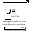
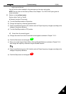
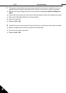
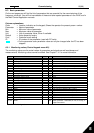
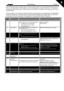
8.3.1 Monitoring values (Control keypad: menu M1)
The monitoring values are the actual values of parameters and signals as well as statuses and
measurements. Monitoring values cannot be edited. See Chapter 7.4.1 for more information.
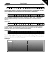
Code Parameter Unit ID Description
V1.1 Output frequency Hz 1 Frequency to the motor
V1.2 Frequency reference Hz 25
V1.3 Motor speed rpm 2 Calculated motor speed
V1.4 Motor current A 3 Measured motor current
V1.5 Motor torque % 4 Calculated actual torque/nominal torque of the unit
V1.6 Motor power % 5 Calculated actual power/nominal power of the unit
V1.7 Motor voltage V 6 Calculated motor voltage
V1.8 DC-link voltage V 7 Measured DC-link voltage
V1.9 Unit temperature ºC 8 Heat sink temperature
V1.10 Analogue input 1 V 13 AI1
V1.11 Analogue input 2 14 AI2
V1.12 Analogue output current 26 AO1
V1.13 Analogue output current 1, expander board mA 31
V1.14 Analogue output current 2, expander board mA 32
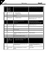
V1.15 DIN1, DIN2, DIN3 15 Digital input statuses
V1.16 DIE1, DIE2, DIE3 33 I/O expander board: Digital input statuses
V1.17 RO1 34 Relay output 1 status
V1.18 ROE1, ROE2, ROE3 35 I/O exp. board: Relay output statuses
V1.19 DOE 1 36 I/O exp. board: Digital output 1 status
V1.20 PID Reference % 20 In percent of the maximum frequency
V1.21 PID Actual value % 21 In percent of the maximum actual value
V1.22 PID Error value % 22 In percent of the maximum error value
V1.23 PID Output % 23 In percent of the maximum output value
V1.24 Autochange outputs 1, 2, 3 30 Used only in pump and fan control
V1.25 Mode 66
Shows the current operating mode selected with the
Start-up Wizard: 1=Standard, 2= Fan, 3= Pump, 4=
High Performance
Table 8-1. Monitoring values