


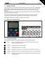
Control Keypad 59(96)
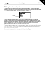
7
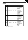
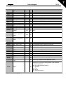
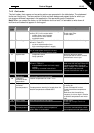
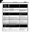
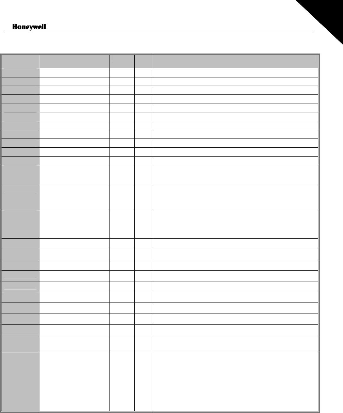
Code Signal name Unit ID Description
V1.1
Output frequency Hz 1 Frequency to the motor
V1.2
Frequency reference Hz 25
V1.3
Motor speed rpm 2 Calculated motor speed
V1.4
Motor current A 3 Measured motor current
V1.5
Motor torque % 4 Calculated actual torque/nominal torque of the motor
V1.6
Motor power % 5 Calculated actual power/nominal power of the motor
V1.7
Motor voltage V 6 Calculated motor voltage
V1.8
DC-link voltage V 7 Measured DC-link voltage
V1.9
Unit temperature ºC 8 Heat sink temperature
V1.10
Analogue input 1 13 AI1
V1.11
Analogue input 2 14 AI2
V1.12
Analogue output
current
mA 26 AO1
V1.13
Analogue output
current 1, expander
board
mA 31
V1.14
Analogue output
current 2, expander
board
mA 32
V1.15
DIN1, DIN2, DIN3
15
Digital input statuses
V1.16
DIE1, DIE2, DIE3
33
I/O expander board: Digital input statuses
V1.17
RO1
34
Relay output 1 status
V1.18
ROE1, ROE2, ROE3
35
I/O exp. board: Relay output statuses
V1.19
DOE 1
36
I/O exp. board: Digital output 1 status
V1.20
PID Reference %
20
In percent of the maximum process reference
V1.21
PID Actual value %
21
In percent of the maximum actual value
V1.22
PID Error value %
22
In percent of the maximum error value
V1.23
PID Output %
23
In percent of the maximum output value
V1.24
Autochange outputs
1,2,3
30
Used only in
P
ump and
F
an
C
ascade control
V1.25
Mode
66
Shows the current drive configuration mode selected
with start-up wizard:
0
= No mode selected (Default)
1
= Standard
2
= Fan
3
= Pump
4
= High performance
Table 7-2. Monitored signals