


Cabling and connections 45(96)
6
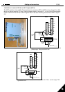
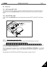
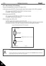
6.2.4 Control I/O
Terminal Signal Description
1 +10V
ref
Reference output Voltage for potentiometer, etc.
2 AI1+
Analogue input, voltage range
0—10V DC.
Voltage input frequency reference
3 AI1- I/O Ground Ground for reference and controls
4 AI2+
5 AI2-
/GND
Analogue input, current range
0—20mA
Current input frequency reference
6 +24V Control voltage output Voltage for switches, etc. max 0.1 A
7
GND I/O ground Ground for reference and controls
8 DIN1 Start forward (programmable) Contact closed = start forward
9 DIN2 Start reverse (programmable) Contact closed = start reverse
10 DIN3 Preset speed selection 1
(programmable)
Contact closed = Preset speed 1
11 GND
I/O ground Ground for reference and controls
18 AO1+
19 AO1-
Output frequency
Analogue output
Programmable
Range 0—20 mA/R
L
, max. 500
Ω
A RS 485 Serial bus Differential receiver/transmitter
B RS 485 Serial bus Differential receiver/transmitter
30 +24V 24V aux. input voltage Control power supply backup
21 RO1
22 RO1
23 RO1
Relay output 1
FAULT
Programmable
Table 6-7. Default I/O configuration.
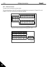
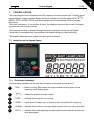
Terminal Signal Description
12 +24V
+24 V DC Control voltage output; voltage for
switches etc.
13 GND I/O ground Ground for reference and controls
14 Exp DIN1 Preset speed selection 2
(programmable)
Contact closed = Preset speed 2
15 Exp DIN2 Fault Reset
(programmable)
Contact closed = Fault reset
16 Exp DIN3 Disable PID (PID control
selection)
(Programmable)
Contact closed = Disable PID
25 Exp RO1
26 Exp RO1
Expander Relay output 1 (NO)
RUN
Programmable
28 TI+
29 TI-
Motor Thermistor input Active = Fault, stop according to defined
method
Table 6-8. Additional inputs in NXL HVAC (available as option for NXL Compact)
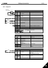
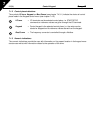
Terminal Signal Description
1 +10V
ref
Reference output Voltage for potentiometer, etc.
2 AI1+
or
DIN 4
Analogue input, voltage range
0—10V DC
Voltage input frequency reference (MF2-3)
Voltage/current input frequency reference
(MF4-MF6)
Can be programmed as DIN4
3 AI1- I/O Ground Ground for reference and controls
4 AI2+
5 AI2-
/GND
Analogue input, voltage range
0—10V DC or current range
0—20mA
Voltage or current input frequency
reference
6 + 24 V Control voltage output
7 GND I/O ground Ground for reference and controls
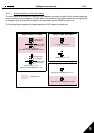
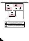
Table 6-9. AI1 configuration, when programmed as DIN4
Reference
Potentiometer 1-10
k
Ω
mA