


F-54F-54
PRECISION TIG 275
TROUBLESHOOTING & REPAIR
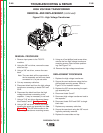
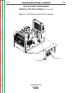
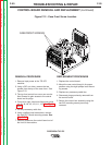
SCR BRIDGE ASSEMBLY REMOVAL AND REPLACEMENT (continued)
REMOVAL PROCEDURE
1. Remove input power to the TIG 275
machine.
2. Using the 3/8” nut driver, remove the case
sides and top.
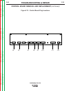
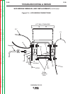
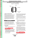
3. Label and cut leads G1 and G2. See
Figure F.14.
4. Label and cut leads G3 and G4. See
Figure F.14.
5. Remove the 1/2 “ nut securing leads B and
217. See Figure F.14.
6. Using a 7/16” nut driver, disconnect Pos.
lead and lead 218.See Figure F.14.
7. Using a 1/2” nut driver, disconnect Pos.
lead and lead 218. See Figure F.14.
8. Using a 1/2” nut driver, remove lead 216
and aluminum lead X1 connecting to the
main transformer. See Figure F.14. Note
washer placement upon removal.
9. Using a 1/2” nut driver, disconnect lead
220A and shunt from the output bridge. See
Figure F.14.
10. Using a 3/8” nut driver, remove the four
SCR bridge mounting bolts. Note insulator
washer placement upon removal.
REPLACEMENT PROCEDURE
1. Replace the SCR bridge.
2. Replace the four SCR bridge mounting
bolts previously removed.
Note: Be sure to replace insulating wash-
ers in their proper positions.
3. Reconnect lead 218 and Pos. lead previ-
ously removed.
4. Replace the shunt and lead 220A previous-
ly removed.
5. Replace the 1/2” bolt securing lead 216 and
the aluminum lead X1 originating from the
main transformer.
6. Reconnect the negative lead to the free
wheeling diode.
7. Replace the 1/2” bolt securing leads B and
217 previously removed.
8. Reconnect leads G1, G2, G3, and G4.
Splice, solder and insulate as necessary.
9. Replace case sides and top.
Return to Section TOC Return to Section TOC Return to Section TOC Return to Section TOC
Return to Master TOC Return to Master TOC Return to Master TOC Return to Master TOC