


F-26F-26
PRECISION TIG 275
Return to Section TOC Return to Section TOC Return to Section TOC Return to Section TOC
Return to Master TOC Return to Master TOC Return to Master TOC Return to Master TOC
TROUBLESHOOTING & REPAIR
PROTECTION BOARD TEST (continued)
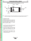
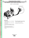
1. Using a 3/8” nut driver, remove the case top
and sides.
2. Check that P5 is connected to J5, not J5A.
See the Wiring Diagram.
3. Unplug P5 from the control board. Measure
resistance at P5. See Figure F3. See tables
below.
4. If the readings above are OK, the protection
board is OK. If not, go to step 5.
5. Unplug P23 from the protection board and
check continuity from P23 to P5. If OK, go
to step 6. See Wiring Diagram.
6. Unplug P22 from protection board. Measure
resistance at P22. See Tables.
7. If readings below are OK, protection board
is bad.
8. If readings below are wrong, remote amptrol
or remote receptacle is bad.
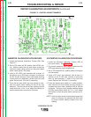
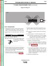
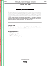
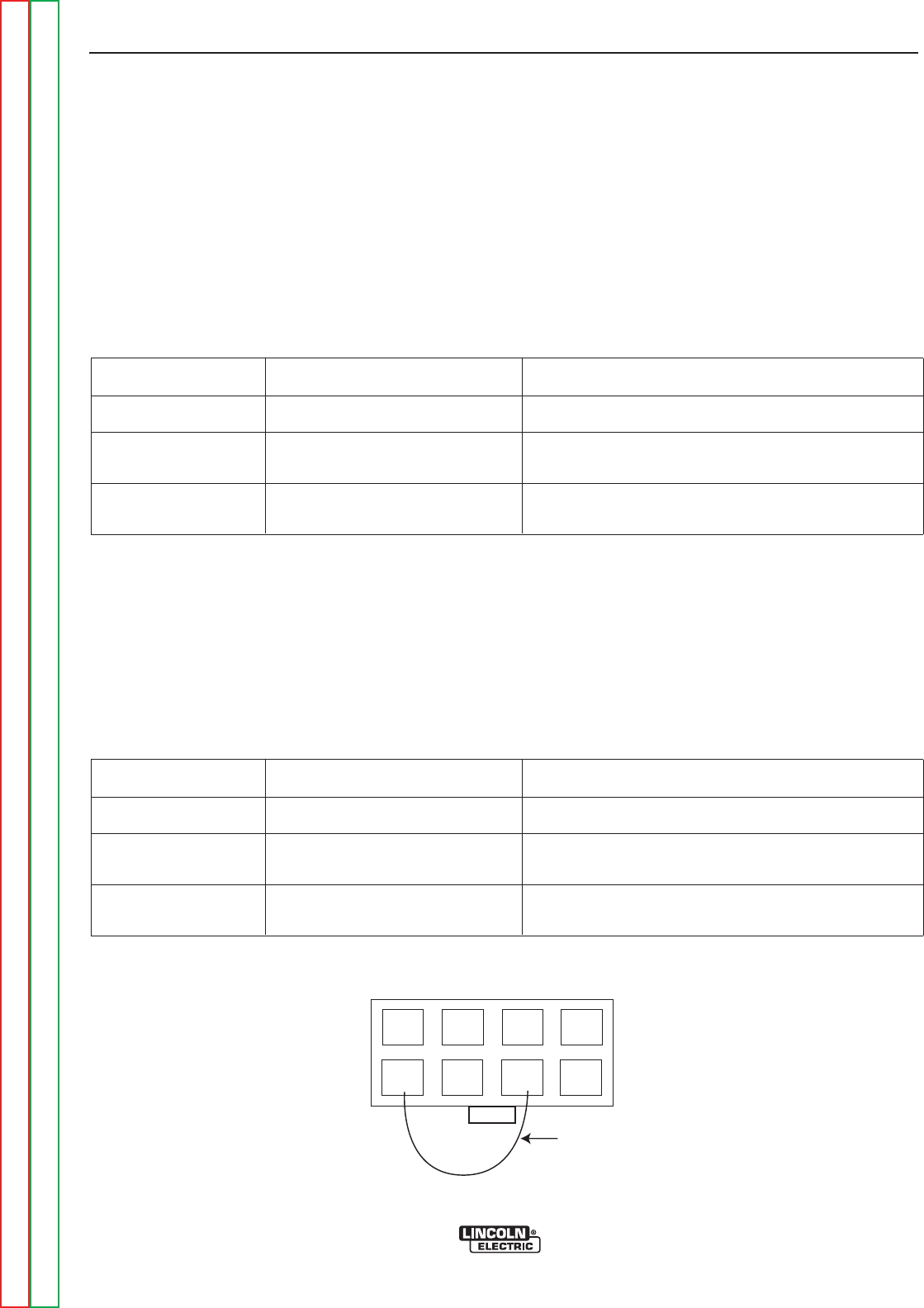
FIGURE F.3 – Plug J5 (viewed from pin end)
1
567
8
4
3
2
Jumper
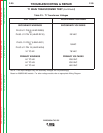
Table F.1
Table F.2
RESISTANCE BETWEEN
Pins 5 & 7
Open when trigger open, short when trigger closed.
Increasing from 0 to 10K when working on remote
amptrol from min. to max.
Decreasing from 10K to 0 when working on remote
amptrol from min. to max.
TRIGGER
B-A
B-C
Pins 3 & 4
Pins 2 & 3
READING
RESISTANCE BETWEEN
Pins 3 & 6
Open when trigger open, short when trigger closed.
Increasing from 0 to 10K when working on remote
amptrol from min. to max.
Decreasing from 10K to 0 when working on remote
amptrol from min. to max.
TRIGGER
B-A
B-C
Pins 1 & 2
Pins 1 & 4
READING