


E-5E-5
PRECISION TIG 275
Return to Section TOC Return to Section TOC Return to Section TOC Return to Section TOC
Return to Master TOC Return to Master TOC Return to Master TOC Return to Master TOC
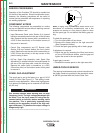
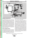
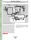
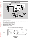
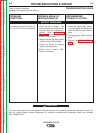
DC WELDING OUTPUT
When the polarity switch is placed in either DC position, the
AC voltage from the main transformer secondary is applied
to the SCR bridge. The SCR bridge and choke circuits are
connected in the conventional full wave bridge and filter
configuration, resulting in a controlled DC output. Since
the choke is in series with the negative leg of the bridge
and also in series with the welding load, a filtered DC is
applied to the output terminals. The bypass board pro-
tects the internal circuitry from interference.
When the machine is in the DC mode, the background cir-
cuitry provides an added boost of voltage to the output
terminals. This circuitry is controlled by the control board.
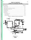
THEORY OF OPERATION
FIGURE E.5 – DC WELDING OUTPUT
P
OWER
S
WITCH
RECONNECT
PANEL
OPTIONAL POWER
FACTOR
P
OLARITY
SWITCH
BYPASS BOARD
WORK
FRONT
ELECTRODE
R
EAR
ELECTRODE
78 VAC
X1
X2
AC
AC
DC
DC
SHUNT
CHOKE
HIGH FREQUENCY
TRANSFORMER
HIGH VOLTAGE
TRANSFORMER
THERMOSTAT
1
15 VAC
115 VAC
115 VAC
FAN
GATE LEADS
FEEDBACK
GAS
SOLENOID
115 VAC
115 VAC
LED's
THERMOSTAT
2
0 VAC
20 VAC
CONTROL BOARD
BACKGROUND
CIRCUIT
FROM
C
ONTROL
BOARD
63.5 VAC
CORRECTION
C
APACITORS
REAR GANG
SCR
BRIDGE
A
DVANCED CONTROL
P
ANEL RECEPTACLE
MINIMUM
OUTPUT
C
ONTROL
MAXIMUM
OUTPUT
CONTROL
P
ROTECTION
BOARD
REMOTE
R
ECEPTACLE
METER
STICK
TIG
SWITCH
BALANCE
CONTROL
POST
FLOW
LOCAL/REMOTE
SWITCH
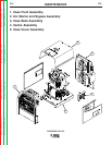
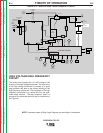
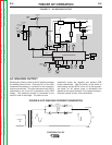
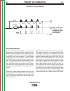
FIGURE E.6 DC WELDING CURRENT GENERATION
G
G
G
G
CHOKE
ELECTRODE
WORK
DC
PRIMARY
10