


F-50F-50
PRECISION TIG 275
TROUBLESHOOTING & REPAIR
CONTROL BOARD REMOVAL AND REPLACEMENT (continued)
REMOVAL PROCEDURE
1. Remove input power to the TIG 275
machine.
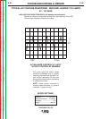
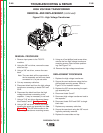
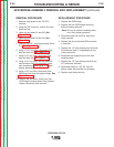
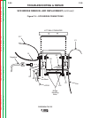
2. Using a 3/8” nut driver, remove the two
screws from the top of the case front. See
Figure F.12.
3. The top front control box cover can now be
tilted forward to gain access to the control
board and its plugs.
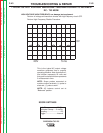
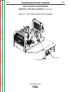
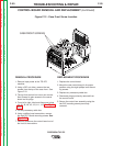
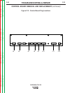
4. From left to right, label and disconnect plugs
J4, J5, J6, J8, J9, J10, J11, J12. See Figure
F.13.
5. Cut any necessary cable ties.
6. Using a phillips head screwdriver, remove
the eight P.C. Board mounting screws. See
Figure F.13.
7. Carefully maneuver the control board out of
the front of the machine.
REPLACEMENT PROCEDURE
1. Replace the control board.
2. Mount the new control board in its proper
position using the eight phillips head mount-
ing screws.
3. Replace any necessary cable ties.
4. Reconnect plugs previously removed from
the control board.
5. Secure the control box assembly using the
two 3/8” mounting screws previously
removed.
R
E
M
O
R
E
M
O
T
E
T
E
L
O
C
A
L
L
O
C
A
L
M
A
X
I
M
U
M
M
A
X
I
M
U
M
D
I
S
P
L
A
D
I
S
P
L
A
YY
M
I
N
I
M
U
M
M
I
N
I
M
U
M
M
O
D
E
M
O
D
E
A
A
C
B
C
B
A
L
A
N
C
E
A
L
A
N
C
E
P
O
S
T
F
L
O
P
O
S
T
F
L
O
WW
D
C
O
N
O
F
F
PO
W
ER
A
C
D
C
+
P
RE
CIS
IO
N TIG
T
M
3
7
5
T
H
E
L
I
N
C
O
L
N
E
L
E
C
T
R
I
C
C
O
M
P
A
N
Y
C
L
E
V
E
L
A
N
D
,
O
H
I
O
U
S
A
D
O
N
O
T
S
W
I
T
C
H
W
H
I
L
E
W
E
L
D
I
N
G
SQ
U
A
R
E
W
A
VE
PO
W
ER
SO
U
R
C
E
f
e
a
t
u
r
i
n
g
.
.
.
M
I
C
R
O
S
T
A
R
T
T
M
T
E
C
H
N
O
L
O
G
Y
~
W
A
R
N
I
N
G
L
IN
C
O
LN
E
L
E
C
TR
IC
!
CASEFRONT SCREWS
Figure F.12 - Case Front Screw Location
Return to Section TOC Return to Section TOC Return to Section TOC Return to Section TOC
Return to Master TOC Return to Master TOC Return to Master TOC Return to Master TOC