


E-2E-2
PRECISION TIG 275
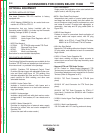
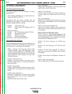
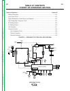
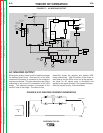
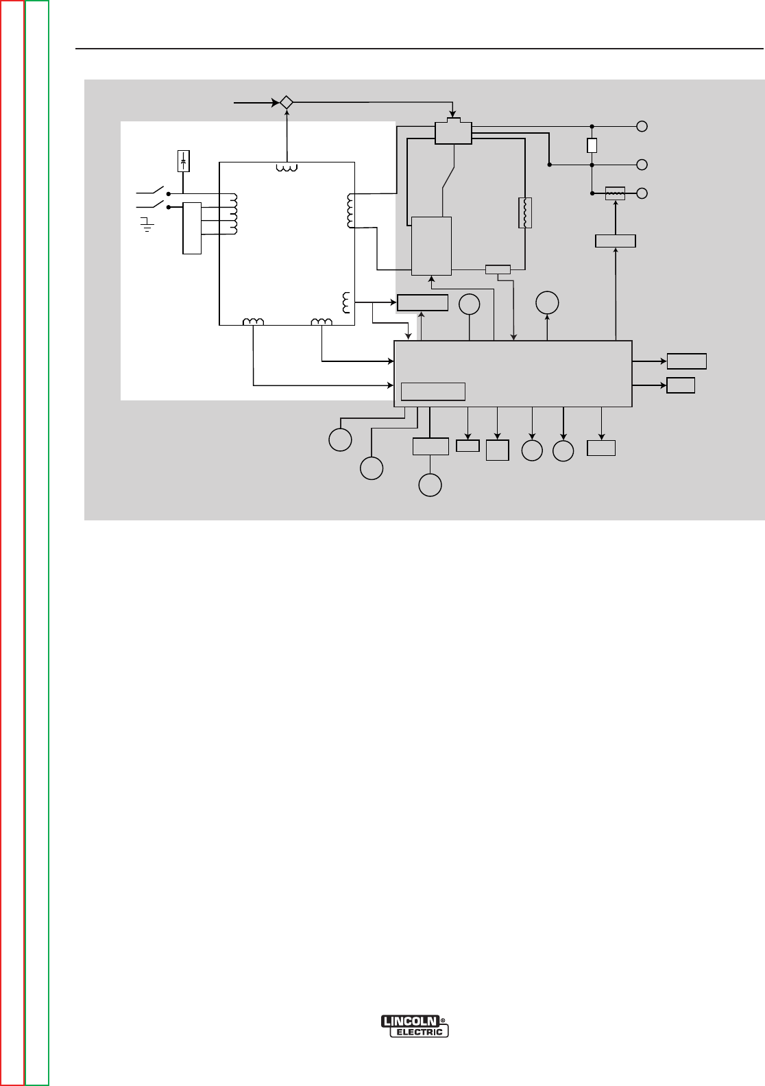
FIGURE E.2 – GENERAL DESCRIPTION AND INPUT POWER CIRCUIT
POWER
SWITCH
RECONNECT
PANEL
O
PTIONAL POWER
FACTOR
POLARITY
SWITCH
B
YPASS BOARD
WORK
FRONT
E
LECTRODE
R
EAR
ELECTRODE
78 VAC
X1
X2
A
C
AC
D
C
DC
S
HUNT
CHOKE
HIGH FREQUENCY
TRANSFORMER
HIGH VOLTAGE
TRANSFORMER
T
HERMOSTAT
1
15 VAC
115 VAC
115 VAC
FAN
GATE LEADS
FEEDBACK
GAS
SOLENOID
115 VAC
115 VAC
LED's
THERMOSTAT
20 VAC
2
0 VAC
CONTROL BOARD
B
ACKGROUND
CIRCUIT
FROM
C
ONTROL
BOARD
63.5 VAC
CORRECTION
CAPACITORS
REAR GANG
SCR
BRIDGE
ADVANCED CONTROL
PANEL RECEPTACLE
MINIMUM
OUTPUT
CONTROL
MAXIMUM
OUTPUT
CONTROL
PROTECTION
BOARD
REMOTE
RECEPTACLE
METER
STICK
TIG
S
WITCH
BALANCE
CONTROL
POST
FLOW
LOCAL/REMOTE
SWITCH
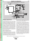
GENERAL DESCRIPTION
The PRECISION TIG 275 is part of a new family of
industrial arc welding power sources able to provide
constant current and single range square wave AC/DC
Tig (GTAW) with new MicroStart
TM
Technology. It incor-
porates independent presettable minimum and maxi-
mum output control with built-in high frequency stabi-
lization for continuous AC Tig welding and reliable DC
Tig starting. The Precision TIG 275 also has AC/DC
stick (SMAW) capabilities. This new design includes
advanced features such as a digital meter, presettable
controls, auto balance
TM
, fan as needed and timers for
fixed preflow and variable post flow of shielding gas. It
features a stick output terminal (front) and a universal
Tig torch connection box (rear) for simultaneous, but
separate, electrode outputs.
INPUT POWER CIRCUIT
The desired single-phase input power is connected to
the PRECISION TIG 275 through the power switch to
the reconnect panel located in the rear of the machine.
The machine can be configured for any one of three
input voltages (208 VAC, 230 VAC or 460 VAC) by con-
necting the jumper strap to the appropriate terminal on
the reconnect panel. When the input power switch is
turned “on,” the input voltage is applied directly to the
primary winding of the main transformer.
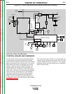
The main transformer changes the high voltage, low
current input power to a low voltage, high current out-
put available at the main secondary winding (X1 and
X2). This 78 VAC winding supplies power to the weld-
ing arc. In addition, four auxiliary windings are incor-
porated in the main transformer. The 115 VAC winding
supplies power to the 115 VAC receptacle. Through
the control board, it also powers the gas solenoid, the
high voltage transformer, and the cooling fan. The
cooling fan is activated only when welding current is
sensed. The 63.5 VAC winding provides power for the
DC background current. This circuit is active in the DC
TIG welding mode. The 20 VAC windings are included
in the main transformer assembly. The 20 VAC winding
is rectified on the control board and is used in the trig-
ger circuitry. The other 20 VAC winding is used by the
control board for phase detection. This AC voltage is
also rectified to several DC voltages and regulated to
+15 VDC and +5 VDC power supplies that operate the
circuitry on the control board.
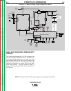
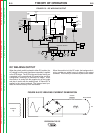
NOTE: Unshaded areas of Block Logic Diagram are the subject of discussion.
Return to Section TOC Return to Section TOC Return to Section TOC Return to Section TOC
Return to Master TOC Return to Master TOC Return to Master TOC Return to Master TOC
THEORY OF OPERATION