


F-20F-20
PRECISION TIG 275
Return to Section TOC Return to Section TOC Return to Section TOC Return to Section TOC
Return to Master TOC Return to Master TOC Return to Master TOC Return to Master TOC
TROUBLESHOOTING & REPAIR
METER CALIBRATION ADJUSTMENTS (continued)
CALIBRATION CHECK
The Digital Meter Calibration Trimmer is located on the
back of the meter housing near the right side connec-
tor plug (with two leads and a jumper attached). This
trimmer adjusts calibration of the meter used for both
ammeter and voltmeter readings, so its calibration
should be checked first, as follows:
1. Set the TIG mode and, without closing the arc start
switch, preset the panel maximum output control so
the panel digital meter reads 200 amps.
2. Using a DC (avg.) digital test voltmeter with at least
0.5% accuracy at 1,000v, measure the DC voltage
between (+) pin 2 (lead #303) and (-) pin 1 (lead
#306) at the right side meter plug (nearest the trim-
mer).
3. This voltage should match the 200A panel meter
reading (as 0.200v, or 200mv) within 1%. If not,
adjust the trimmer so that the panel meter accuracy
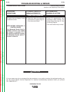
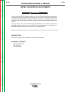
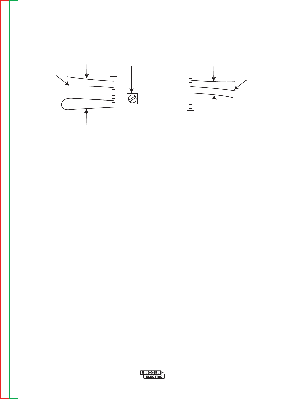
is corrected. (See Figure F.1)
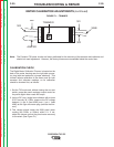
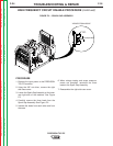
FIGURE F.1 – TRIMMER
TRIMMER
306
301
304B
302
303
JUMPER
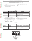
Note: The Precision TIG meter circuits are factory calibrated for the accuracy of the ammeter and voltmeter and
should not need adjustment. However, the factory trimmers are accessible inside the control box: