


F-60F-60
PRECISION TIG 275
TROUBLESHOOTING & REPAIR
SCR REMOVAL AND REPLACEMENT (continued)
SPECIAL INSTRUCTIONS
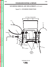
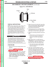
NOTE: Before disassembling the existing recti-
fier, note toward which heat sink the outer
metal ring of the power SCR is mounted. Also,
note the positioning of the gate lead of the
SCR. Failure to reinstall the new SCR in the
same orientation as the original may result in
subsequent damage to the new SCR and
other components of the welder. See Figure
F.16.
The unclamping and clamping procedure out-
lined below is critical for the prevention of
internal SCR damage. Failure to follow this
procedure may result in subsequent damage
of the SCR. Handle all SCRs with care.
PROCEDURE
1. Remove the main input supply power to the
machine.
2. Perform the SCR/Diode Rectifier
Assembly Removal procedure.
3. Using a 7/16” open end wrench, alternately
loosen nuts 1/2 turn each until heat sinks
are loose. Remove nuts and leaf spring. IT
IS RECOMMENDED THAT NEW HARD-
WARE, LEAF SPRING AND HOUSING BE
USED FOR ASSEMBLY.
4. Remove the old SCR.
5. Clean the area on the heat sink around the
SCR mounting surface, using a putty knife
or similar tool. DO NOT SCRATCH THE
SCR MOUNTING SURFACE.
6. Polish each heat sinkʼs mounting surface
using NO.000 fine steal wool. Wipe surface
clean with a lint free cloth or paper towel.
7. Inspect the mounting surfaces of each new
SCR.
a. Remove all burrs and wipe clean. Do
not use steel wool or any abrasive
cleanser on the SCR mounting sur-
faces.
8. Apply a thin (0.001” to 0.003”) layer of
PENETROX A-13 (Lincoln Electric #E2529)
or PENTROX A, heat sink compound, to
each heat sinkʼs SCR mounting surface.
a. Care must be used to prevent foreign
material contamination of the SCR to
heat sink junction.
9. Place the new SCR between the heat
sinks. Be sure that the outer metal ring of
the SCR is facing toward the same heat
sink as the old SCRʼs metal ring. Be sure
that the roll pin of the heat sink engages
the “hole” in the SCR. The SCR contact
surfaces must sit flat against both heat sink
surfaces.
10. Perform the SCR/Diode Rectifier
Assembly Replacement Procedure.
11. Replace the case sides and top.
Cathode
Gate
Anode
Outer Metal
Ring
Figure F.16 - SCR DETAILS
Return to Section TOC Return to Section TOC Return to Section TOC Return to Section TOC
Return to Master TOC Return to Master TOC Return to Master TOC Return to Master TOC
CAUTION