


F-6F-6
PRECISION TIG 275
TROUBLESHOOTING & REPAIR
Observe Safety Guidelines TROUBLESHOOTING GUIDE
detailed in the beginning of this manual.
If for any reason you do not understand the test procedures or are unable to perform the test/repairs safely, con-
tact the Lincoln Electric Service Department for electrical troubleshooting assistance before you proceed.
Call 1-888-935-3877.
PROBLEMS
(SYMPTOMS)
POSSIBLE AREAS OF
MISADJUSTMENT(S)
RECOMMENDED
COURSE OF ACTION
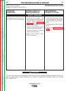
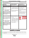
OUTPUT PROBLEMS
No output from the machine in
either Stick or TIG modes. The
thermal light is on.
NOTE: BEFORE REPLACING A
CONTROL BOARD
If an Advanced Control Panel is
installed, remove it and replace
the Jumper in connector J-3. If
the machine functions normally,
the Advanced Process panel or
harness is defective.
1. The welding application may
have exceeded the recommend-
ed duty cycle. Allow the fan to
cool the until the thermal light is
off.
2. The air louvers may be blocked.
Remove the air obstruction and
allow the unit to cool.
1. One of the thermostats may be
faulty. Check or replace. See
the Wiring Diagram.
2. Check for loose or faulty wires
on the thermostats and associat-
ed circuitry. See the Wiring
Diagram.
3. The fan motor may be faulty or
mechanically obstructed. The
fan should run when welding or
when a thermostat is open.
4. The control board may be faulty.
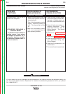
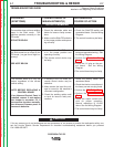
The machine does not respond (no
gas flow, no high frequency and no
open circuit voltage) when the arc
start switch or Amptrol is activated.
The thermal light is not lit.
NOTE: BEFORE REPLACING A
CONTROL BOARD
If an Advanced Control Panel is
installed, remove it and replace
the Jumper in connector J-3. If
the machine functions normally,
the Advanced Process panel or
harness is defective.
1. Make sure the machine is in the
TIG mode.
2. The Amptrol or arc start switch
may be defective. Check for
continuity ( zero ohms) between
pins “D” and “E” on the cable
connector when the Amptrol or
arc start is pressed.
3. Check the Local/Remote switch
for proper operation.
1. Perform the Protection Board
Test.
2. Perform the T1 Transformer
Test.
3. The control board may be faulty.
Return to Section TOC Return to Section TOC Return to Section TOC Return to Section TOC
Return to Master TOC Return to Master TOC Return to Master TOC Return to Master TOC
CAUTION