


F-38F-38
PRECISION TIG 275
Return to Section TOC Return to Section TOC Return to Section TOC Return to Section TOC
Return to Master TOC Return to Master TOC Return to Master TOC Return to Master TOC
TROUBLESHOOTING & REPAIR
ACTIVE SCR TEST (continued)
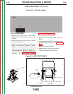
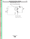
6. Connect SCR into the test circuit as shown
in Figure F.8. (A)Lead to anode (C) lead to
cathode and (G) lead to the gate.
7. Close switch SW-1 (Switch SW-2 should be
open). The voltmeter should read zero. If
the voltmeter reads higher than zero, the
SCR is shorted.
8. With switch SW-1 closed, close switch SW-2
for two seconds and release. The voltmeter
should read 3 to 6 volts before and after
switch SW-2 is released. If the voltmeter
does not read, or reads only while SW-2 is
depressed, the SCR or battery is defective.
(Repeat Battery Test Procedure described in
Step 5.)
9. Open switch SW-1, disconnect the gate lead
(G) and reverse the (A) and (C) leads on
the SCR. Close switch SW-1. The voltmeter
should read zero. If the voltage is higher
than zero, the SCR is shorted.
10. Replace any SCRs that do not pass the
test. See SCR Bridge Assembly
Removal and Replacement.
11. Replace plug J4 on the control board.
12. Replace the case sides and top.
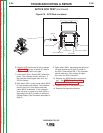
D
IODE D1
SCR4 CATHODE
S
CR3 / SCR4 ANODE
SCR3 CATHODE
SCR2 ANODE
S
CR1 / SCR2 CATHODE
S
CR1 ANODE
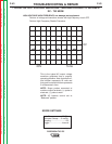
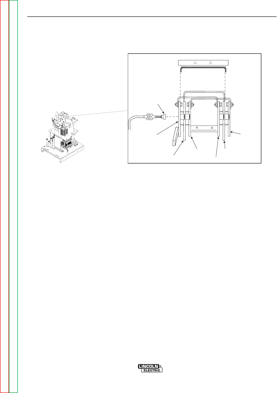
LIFT BAIL STABILIZER
Figure F.9 - SCR Gate Locations