


E-6E-6
PRECISION TIG 275
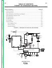
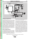
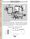
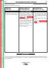
AC WELDING OUTPUT
Rotating the polarity switch to the AC position changes
the welding power circuit. One lead (X1) of the main
transformer secondary is connected to the machineʼs
output work terminal. The other secondary lead (X2) is
connected to one of the AC connections of the SCR
bridge. The electrode terminal is connected to the
other AC side of the bridge. The choke is now
electrically across the negative and positive SCR
bridge connections. With the ability of the choke to
store energy and the SCRs to turn on at the appropri-
ate times, an AC square wave is developed and
applied to the output terminals. The bypass board pro-
tects the internal circuitry from interference.
THEORY OF OPERATION
FIGURE E.7 – AC WELDING OUTPUT
P
OWER
S
WITCH
RECONNECT
PANEL
OPTIONAL POWER
FACTOR
POLARITY
SWITCH
BYPASS BOARD
WORK
F
RONT
ELECTRODE
REAR
ELECTRODE
78 VAC
X
1
X
2
A
C
A
C
DC
DC
S
HUNT
CHOKE
HIGH FREQUENCY
TRANSFORMER
HIGH VOLTAGE
TRANSFORMER
THERMOSTAT
115 VAC
115 VAC
115 VAC
F
AN
GATE LEADS
FEEDBACK
GAS
SOLENOID
115 VAC
115 VAC
LED's
THERMOSTAT
20 VAC
20 VAC
CONTROL BOARD
BACKGROUND
CIRCUIT
FROM
CONTROL
BOARD
63.5 VAC
CORRECTION
CAPACITORS
REAR GANG
SCR
B
RIDGE
A
DVANCED CONTROL
PANEL RECEPTACLE
MINIMUM
OUTPUT
CONTROL
MAXIMUM
OUTPUT
CONTROL
P
ROTECTION
BOARD
REMOTE
R
ECEPTACLE
METER
STICK
TIG
S
WITCH
BALANCE
CONTROL
POST
FLOW
LOCAL/REMOTE
SWITCH
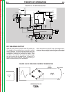
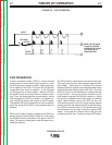
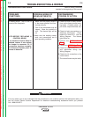
FIGURE E.8 DC WELDING CURRENT GENERATION
G
CHOKE
ELECTRODE
WORK
DC
PRIMARY
10
G
G
G
Return to Section TOC Return to Section TOC Return to Section TOC Return to Section TOC
Return to Master TOC Return to Master TOC Return to Master TOC Return to Master TOC