


INSTALLATION
LN-15
A-4 A-4
Return to Section TOC Return to Section TOC Return to Section TOC Return to Section TOC
Return to Master TOC Return to Master TOC Return to Master TOC Return to Master TOC
WELD CABLE CONNECTIONS
ELECTRIC SHOCK CAN KILL.
• Only a qualified electrician should
connect the electrode leads to the
LN-15. Connections should be
made in accordance with all local
and national electrical codes.
Failure to do so may result in bodi-
ly injury or death.
------------------------------------------------------------------------
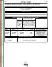
The size of the electrode cable and work cable must be
sufficient for the maximum weld current and total cable
length used.
To avoid interference problems with other equipment
and to achieve the best possible operation, route all
cables directly to the work or wire feeder. Avoid exces-
sive lengths and do not coil excess cable. Be sure the
connection to the work makes tight metal-to-metal
electrical contact. (See Table A.1)
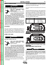
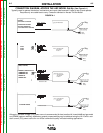
ELECTRODE CONNECTION
Route the electrode cable through the strain relief in
the rear of the case. Connect the electrode cable to the
LN-15 input stud using the mounting hardware provid-
ed. Secure the cable by tightening the strain relief.
All domestic models are supplied with pigtail for cus-
tomers that prefer to make a taped and bolted connec-
tion externally. CE models have a male twist connector
for the electrode connection.
WORK CONNECTION
Connect a work lead of sufficient size between the
proper output stud on the power source and the work.
Be sure the connection to the work makes tight metal
to metal electrical contact. Poor work lead connections
can result in poor welding performance.
POWER SOURCE CONNECTION
The LN-15 can be used with any DC welding power
source. A constant voltage power source is recom-
mend; however, the LN-15 can also be used with a
constant current power source as long as the open cir-
cuit voltage is less than 110VDC.
To prevent possible damage to the LN-15, do not
connect the LN-15 to non-Lincoln TIG or square
wave power sources. TIG high frequency should
never be applied to the LN-15.
------------------------------------------------------------------------------------------
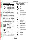
WARNING
CAUTION
Weld Current Total Cable Length
60% Duty (electrode cable + work cable)
Cycle 50 - 100' 100 - 150' 150 - 200' 200 - 250'
(15-30 m) (30 - 46m) (46 - 61m) (61m - 76m)
200 Amps 2 AWG 2 AWG 1 AWG 1/0
300 Amps 1 AWG 1 AWG 1/0 2/0
400 Amps 2/0 2/0 3/0 3/0
TABLE A.1
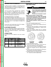
ENGINE DRIVE POWER SOURCE
CONNECTION
The LN-15 has an internal contactor and the electrode
is not energized until the gun trigger is closed. When
the gun trigger is closed the wire will begin to feed and
the welding process is started.
1. Shut the welder off.
2. For electrode Positive polarity welding, connect the
electrode cable to the "+" terminal of the welder and
work cable to the "-" terminal of the welder. For
Electrode Negative welding, connect the electrode
cable to the "-" terminal of the welder and work
cable to the "+" terminal of the welder.
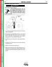
3. Attach the work clip lead from the front of the LN-15
to work using the spring clip at the end of the lead.
This is a control lead to supply current to the wire
feeder motor; it does not carry welding current.
4. Set the MODE switch on the engine drive to CV-
WIRE.
5. Set the WELD TERMINALS switch to WELD TER-
MINALS ON.
6. Set the WIRE FEEDER VOLTMETER switch to
either "+" or "-" as required by the electrode polarity
being used.
7. Set the ARC CONTROL knob to "0" initially and
adjust to suit.
8. Set the IDLE switch to the AUTO position.
Important: Some older engine drives may require
the IDLE switch to be in the HIGH position for prop-
er LN-15 operation.