


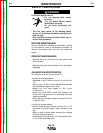

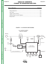

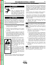
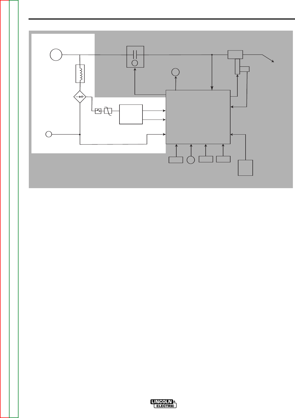
FIGURE E.2 – GENERAL DESCRIPTION & INPUT POWER
CONTACTOR
ELECTRODE
INPUT VOLTAGE
TOROID
ASSEMBLY
FULL
WAVE
BRIDGE
WORK
SENSING
LEAD
ON/OFF
SWITCH
MOV
BOOST
POWER
SUPPLY
BOARD
FEED HEAD
BOARD SUPPLY
DRIVE MOTOR
SUPPLY
"WORK" VOLTAGE FEEDBACK #21
GAS
SOLENOID
"ELECTRODE"
FEEDBACK
VOLTAGE #67
FEED
PLATE
M
O
T
O
R
HALL
EFFECT
MODULE
RPM FEEDBACK
ARMATURE
WELDING
GUN
DISPLAY
BOARD
COLD
INCH
SWITCH
WIRE
FEED
SPEED
CONTROL
TRIGGER
INPUT &
PROCEDURE
TRIGGER
INTERLOCK
SWITCH
SPI COMMUNICATIONS
SHIELDED CABLE
FEED HEAD
CONTROL BOARD
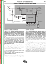
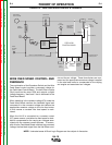
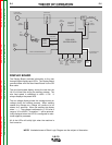
THEORY OF OPERATION
GENERAL DESCRIPTION
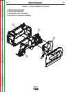
The LN-15 is a lightweight portable semi-automatic
wire feeder. The “Across the Arc” model is capable of
operating with Lincoln DC power sources supplying
between 15VDC to 110VDC. The LN-15 is designed
for semi-automatic use and has a 60% duty cycle rat-
ing.
By attaching the work clip to the work piece and the
LN-15 electrode cable to the Lincoln power source the
LN-15 is ready to feed wire and weld. The LN-15 can
be connected for either welding polarity without any
changes to the LN-15. When the gun trigger is acti-
vated and wire feeds and an internal contactor ener-
gizes the electrode output.
The wire drive is capable of operating in either the con-
stant voltage or the constant current mode. A con-
stant current voltage power source is recommended
for flux-cored arc welding (FCAW) and gas metal arc
welding (GMAW) to obtain code quality results.
For non-critical quality applications a constant current
power source may be used.
The LN-15 comes factory equipped with a K1500-2
Tweco style #2-#4 gun bushing.
The “dual procedure” mode drops the wire feed speed
83% from the original set point. The voltage setting
remains the same.
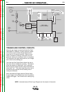
INPUT POWER
The DC voltage supplied from the power source is
applied to the LN-15 through the electrode cable and
the work sensing lead. The voltage is applied to the
full wave bridge through a toroid assembly. When the
ON/OFF switch is put in the ON position the positive
DC voltage from the bridge is applied to the
Boost/Power Supply board through an M.O.V. assem-
bly. This M.O.V. is needed to protect the Boost/Power
board from inductive energy stored in the welding
cables.
The Boost/Power Board takes the weld voltage and
boosts it to 80VDC or the actual arc voltage being
applied. (Whichever is greater). The outputs of the
Boost/Power board are two separate 80VDC+ supply
voltages. One of these is utilized and regulated by the
Feed Head Control board to power the wire drive
motor. The other 80VDC supply is regulated to create
several plus and minus regulated DC supplies. These
+/-15VDC and +/-5VDC supplies are used to power
the electronics within the Feed Head board and other
components in the LN-15 such as the gas solenoid.
E-2 E-2
Return to Section TOC Return to Section TOC Return to Section TOC Return to Section TOC
Return to Master TOC Return to Master TOC Return to Master TOC Return to Master TOC
LN-15