


LN-15
THEORY OF OPERATION
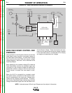
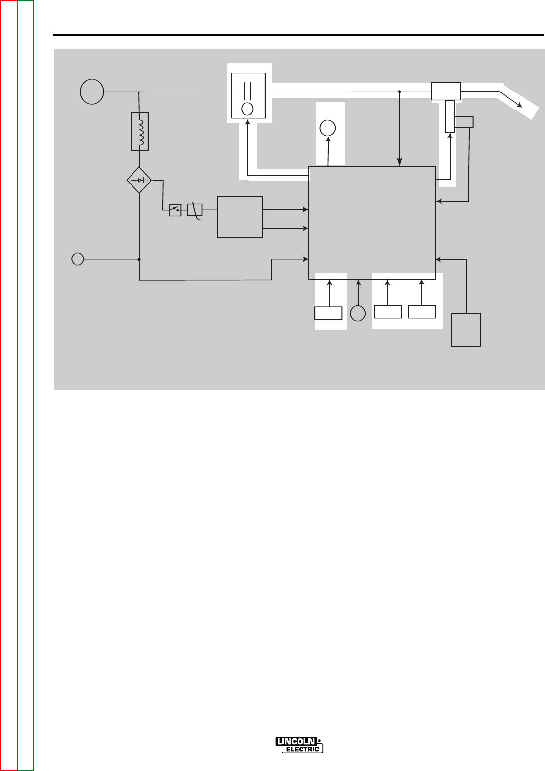
TRIGGER AND CONTROL CIRCUITS
When the gun trigger is closed (activated) the Feed
Head Board is “signaled” to apply armature voltage
to the drive motor, activate the gas solenoid and
close the LN-15 internal contactor. When the con-
tactor is closed the welding current path from the
electrode cable to the conductor block is completed.
This sequence will supply electrode wire, arc voltage
and current to the welding gun.
The Cold Inch/Gas Purge Switch allows the user to
feed wire without closing the contactor. This feature
gives the operator an electrically “cold” electrode
even though the power source’s output terminals are
electrically “hot”. This switch also allows the user to
activate the gas solenoid without feeding wire or
closing the contactor.
When activated the Trigger Interlock Switch keeps
the gun trigger circuit closed even when the operator
releases the trigger. This is useful when making long
welds.
E-3 E-3
Return to Section TOC Return to Section TOC Return to Section TOC Return to Section TOC
Return to Master TOC Return to Master TOC Return to Master TOC Return to Master TOC
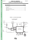
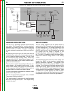
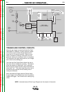
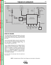
NOTE: Unshaded areas of Block Logic Diagram are the subject of discussion.
FIGURE E.3 – TRIGGER & CONTROL CIRCUITS
CONTACTOR
ELECTRODE
INPUT VOLTAGE
TOROID
ASSEMBLY
FULL
WAVE
BRIDGE
WORK
SENSING
LEAD
ON/OFF
SWITCH
MOV
BOOST
POWER
SUPPLY
BOARD
FEED HEAD
BOARD SUPPLY
DRIVE MOTOR
SUPPLY
"WORK" VOLTAGE FEEDBACK #21
GAS
SOLENOID
"ELECTRODE"
FEEDBACK
VOLTAGE #67
FEED
PLATE
M
O
T
O
R
HALL
EFFECT
MODULE
RPM FEEDBACK
ARMATURE
WELDING
GUN
DISPLAY
BOARD
COLD
INCH
SWITCH
WIRE
FEED
SPEED
CONTROL
TRIGGER
INPUT &
PROCEDURE
TRIGGER
INTERLOCK
SWITCH
SPI COMMUNICATIONS
SHIELDED CABLE
FEED HEAD
CONTROL BOARD