


LN-15
F-12 F-12
Return to Section TOC Return to Section TOC Return to Section TOC Return to Section TOC
Return to Master TOC Return to Master TOC Return to Master TOC Return to Master TOC
TROUBLESHOOTING & REPAIR
TEST PROCEDURE
1. Remove input power to the LN-15.
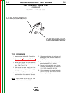
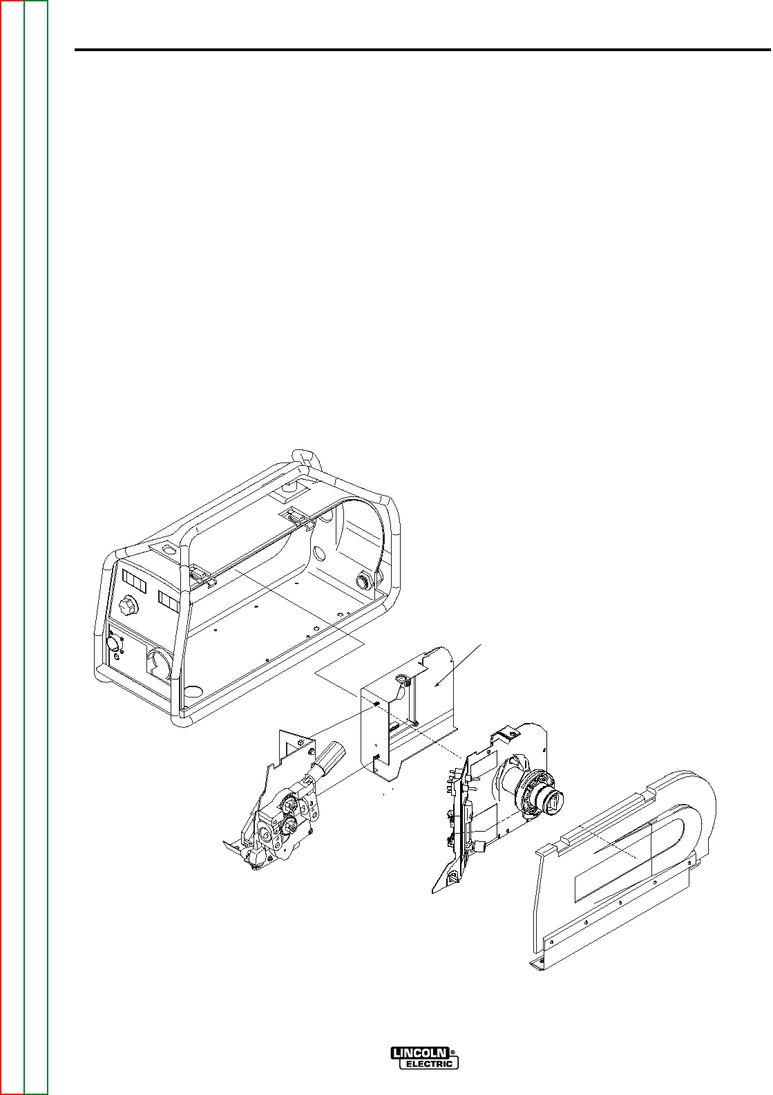
2. Perform the Cover and Spindle Mount removal
procedure.
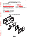
3. Locate the Boost Power Board. See Figure F.1.
4. Apply the correct DC voltage to the LN-15 (15-110
VDC).
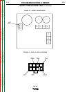
5. Check for the correct input voltage to the Boost
Power Board at leads 526A (+) to 527A(-) (15-110
VDC). See Figure F.3. If the input voltage is not
present check the input rectifier bridge and associ-
iated circuits. See the wiring diagram.
6. Check for approximately 80 VDC at leads 501(+) to
502(-) . See Figure F.3.
7. Check for approximately 80 VDC at leads labeled
POS to NEG. See Figure F.3.
8. If the correct input voltage is present in step 5 and
either of the voltages in steps 6 or 7 are not present
the Boost Power Board is faulty. Replace.
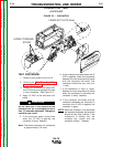
BOOST POWER BOARD
FIGURE F.1 – BOOST POWER BOARD LOCATION
BOOST POWER BOARD TEST (continued)