


Return to Section TOC Return to Section TOC Return to Section TOC Return to Section TOC
Return to Master TOC Return to Master TOC Return to Master TOC Return to Master TOC
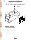
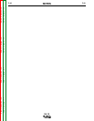
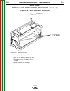
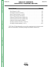
ELECTRICAL DIAGRAMS
G-3
LN-15
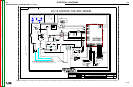
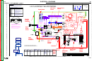
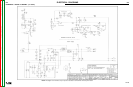
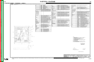
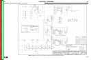
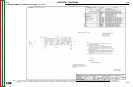
SCHEMATIC - ENTIRE MACHINE - (G4198-1)
EN-170
S
O
L
I
D
E
D
G
E
G4198-1
LN-15 (ACROSS THE ARC)
MACHINE SCHEMATIC
NONE
G4198
E. ENYEDY/KJ
E. ENYEDY
UNLESS OTHERWISE SPECIFIED TOLERANCE
MANUFACTURING TOLERANCE PER E2056
ON 2 PLACE DECIMALS IS ± .02
ON 3 PLACE DECIMALS IS ± .002
ON ALL ANGLES IS ± .5 OF A DEGREE
WITH PUBLISHED STANDARDS.
MATERIAL TOLERANCE (" ") TO AGREE
t
DO NOT SCALE THIS DRAWING
DRAWN BY:
DESIGN INFORMATION
ENGINEER:
APPROVED:
REFERENCE:
EQUIPMENT TYPE:
SUBJECT:
SCALE:
G4198-1
MATERIAL
DISPOSITION:
APPROVAL
DATE:
PROJECT
NUMBER:
NA
CRM35166
1
PAGE ___ OF ___
1
ENGINEERING CONTROLLED
MANUFACTURER:
No
RELEASED A.03 FROM "X"
DOCUMENT
NUMBER:
DOCUMENT
REVISION:
THIS DOCUMENT CONTAINS PROPRIETARY INFORMATION OWNED BY LINCOLN GLOBAL, INC. AND MAY NOT BE DUPLICATED, COMMUNICATED
TO OTHER PARTIES OR USED FOR ANY PURPOSE WITHOUT THE EXPRESS WRITTEN PERMISSION OF LINCOLN GLOBAL, INC.
PROPRIETARY & CONFIDENTIAL:
A
05/27/2003
LN-15 ACROSS THE ARC MODEL
J1,J86
CAVITY NUMBERING SEQUENCE
(COMPONENT SIDE OF P.C. BOARD)
J81,J82
6
5
10
1
3
4
1
2
J85,J87
9
8
16
1
4
6
1
3
GENERAL INFORMATION
ELECTRICAL SYMBOLS PER E1537
COLOR CODE
B - BLACK
W - WHITE
R - RED
U - BLUE
J83,J88
J2,J47,J84
5
4
8
1
526C
-
+
CONTACTOR
300A 60%
250A 100%
WORK
CLIP
BOOST BOARD
2
1
6
3
4
5
J47
8
7
P
OS
527A
502
N
EG
526A
67
21A
A
D
C
B
E
555
J3
554
556
552
553
GAS
SOLENOID
552
550
551
553
TRIGGER
CONNECTOR
578
507
559 (RED)
512
558 (BLK)
512
558
COLD INCH/
GAS PURGE
S1
555
554
556
WIRE FEED SPEED
CONTROL
POTENTIOMETER
21A
527
MOTOR /
GEARBOX
TACH.
67
7
2
1
8
4
3
W
B
B
J2
INPUT ELECTRODE
CABLE CONNECTION
GUN
TRIGGER
INPUT
83%
PROCEDURE
INPUT
320V, 150J
320V, 150J
.0047/.005 mfd,
1400VDC
1M ohms
6
5
21B
567
21
GND-A
1
2
3
MOV ASBLY
GND-B
150V, 300J
MOV ASBLY
501
2.6 VDC @ 50 in/min
27.4 VDC @ 700 in/min
8 sec average Current
limit = 3.5 Amps
(Limit is software set)
Measure B to U
120 Hz @ 50 in/min
1.6 kHz @ 700 in/min
15 VDC Tach Supply
6.5 VDC when gas flowing
Coil measures 21 ohms
83% Input
Trigger Supply
Trigger Input
The 83% procedure reduces the
WFS to 83% of the set point, but
no less than 50 in/min. It is used
most often when pipe welding.
Cold Inch
15 VDC when Inch OFF
0 VDC when Inch ON
15 VDC
Cold Inch
Gas Purge
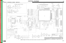
The display board communicates to the feedhead board through the SPI
bus. Only the power supply signals can be monitored during servicing.
The WFS always shows the present WFS.
The voltage display shows the voltage while welding, plus holds the
voltage for 5 seconds after the weld. It shows "- - -" when idle. A negative
"-" sign will automatically be shown when welding with reverse polarity
procedures.
All the LEDs, including those not used, will briefly light on power up. The
LED's not used are visible behind the nameplate when lit.
L11757-1
SPI DISPLAY
WFS Display
Voltage Display
Voltage LED
Not Used
RED
RED
RED RED
YELLOW
DISPLAY P.C. BOARD
2
16
3
4
58
7
10
9
SHIELDED CABLE
DRAIN LEAD
J1
+ 15 VDC SPI
+ 5 VDC SPI
Slave Select
Chip Select 1
Chip Select 2
Chip Select 3
Master In Slave Out
Serial Clock
Master Out Slave In
COM
N.A.
Schematic L11756-x
Electrode Voltage
Pigtail
Bussbar from input
stud to contactor
BRIDGE
RECTIFIER
The rectifier allows the LN-15 to
be powered either electrode
positive or electrode negative
without any switches for the
customer to set.
This large MOV
absorbs the
inductive energy in
the weld cables and
power source when
the contactor
opens.
Located in the control box next
to the Feedhead board.
General Notes:
x
Codes 10864,11033 & 11035 do not support the high/low speed gear
change. Only the high speed (1.8" diameter) gear may be used.
Error
Code
Description Cause and Remedy
Err 0081 Average
motor Over-
current
shutdown
The wire drive has exceeded the current rating:
10 amps for 0.5 seconds or
3.5 amps for 10 seconds.
Wait 45 seconds for the error to reset.
Reduce the current load on the motor by:
Verifying the electrode slides easily through the
liner of the gun.
Reduce the spindle brake resistance.
Reduce the amount of tension in the wire drive
pressure arm.
Use only Lincoln electrodes.
Err 0086 Trigger
lockout
The voltage into the feed head board exceeds 150
VDC.
Some inverters and choppers may have spikes on the
output that charge the capacitors inside the LN-15
beyond limits. If this error occurs, lower the OCV of
the power source. It may be likely that a different
power source is required.
B
o
o
s
t
C
i
r
c
u
i
t
Common
to '-' input
enabling
circuit
COM
ISOLATION
SWITCH (FET)
- INPUT
COM
+ INPUT
COM
MOTOR SUPPLY
FEEDHEAD SUPPLY
- INPUT
R
U
15- 110 VDC
The boost board takes the weld voltage
and boosts it to 80VDC for the rest of
the LN-15. There are two supplies on
the boost board, one for the motor and
the other for the feedhead board. With
two supplies, even if the motor supply
should droop because of heavy loads,
power to the feed head board is not
affected.
80VDC or weld voltage,
whichever is higher
COM
POT Supply
Wiper
Wiper to COM
5 VDC at 700 ipm
0 VDC at 50 ipm
10K Ohms
3-1/2 turns
Coil measures 4.4 ohms.
0 VDC Open
2.3 VDC Closed
12 VDC coil
PWM Controlled
Mode l Ra ng er 8,9 Classic Ranger 250, 305
Commander 300,400,500
(Common Analog
Cont rols)
V350
(Common Digital
Controls)
DC-400, 600 Square Wave TIG
300/355
Mi ller Inverters STT II
K1870-1,-2 Across
the Arc
Recommended
all CV operation.
Recommended for CV
operation. (Wire
Feed Module
Required)
Recommended for CV
operation.
Recommended for
CV operation.
Recommend ed
for CV and CC
operation.
Not recommended
for CC operation
because the
customer may
experience short
contactor life from
inductive nature of
the power source.
Recommende
d for CV
voltage sense
operation.
Not
recommended
for STT
operation.
Not e:
Most semiautomatic
wire welding
processes perform
better using constant
voltage power sources.
Be sure the proper
power source is used
for your application.
Contactor life may be
shortened in
applications using CC
machines with high
OCV.
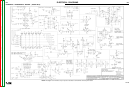
Boost Board
Wire Drive
Circuit
Positive
Voltage
Feedback
Input
Power
Circuit
Input
Voltage
Protection
Contactor
WFS
Control
Circuit
Gun Trigger
Circuit
Inch/Purge
Circuit
Gas Solenoid
Circuit
Motor -
Gas Solenoid +
Gas Solenoid -
Tach COM
2
1
3
4
J82
2
1
6
3
4
5
J83
1
3
4
J81
2
1
3
4
2
1
6
3
4
5
J85
8
7
10
9
11
12
2
16
3
4
5
8
7
10
9
FEED HEAD CONTROL
P.C. BOARD
563
561
POS
SPI
CKTS
V
)HC
niV
-
+
YLPPUS
REWOP
niV+
3-28J
3-18J
6-38J
5-38J
4-28J
4-18J
6
5
8
7
576
562
577
575
Tach Signal
14
13
1
6
15
ROTIN
OMEGATLOV
ROTOM
5
J88
YLPPUS
k
4
1
J86
YLPPUS
REWOP
see power
supply section
molex
5
6
6
J83
2
+15V
-15V
-5V
+5V(TA
+5
COM
+ motor
1200uF
COM
+MOTOR
Vin
INPUT VOLTAGE MONITOR
(MOTORFETS ARE BOTH
OFFWHENINPUT VOLTAGE
DROPS BELOW 20V)
V5+
+
COM
+5V (TACH)
TACH
INPUT
COM
DRIVE
BRAKE
+ MOTOR
PWM
MOTOR
CONTROL
PULSE BYPULSE
PEAK CURRENT
LIMIT (27 AMPS)
AVERAGE
CURRENT
LIMITING
+15V
gas
solenoid
PWM control
ckts
CPLD
MOC
k2
k57.4
COM
INTERNAL
SWITCH
INPUTS
A=1
+
5
V
A=1
WFS
ANALOG
INPUT
V51+
STUPNI
HCTIWS
LANRETXE
k57.4
005
k57.4
005
005
k57.4
OM
4.75k
2k
COM
C
k2
k57.4
+15V
J84
78k
78k
40
+
-
1M
1M
PWM
CONTROL
FOR
CONTACTOR
ARC VOLTAGE
FEEDBACK
I
N
PUT
Schematic G3883
559
Gas Purge
15 VDC when Purge OFF
0 VDC when Purge ON
For programming at LECo factory only.
Not field reprogrammable.
J87
15
1
6
13
12
11
14
9
10
7
8
5
4
3
61
2
COM
NEG
501
502
COM
Motor +
J84
FEEDPLATE
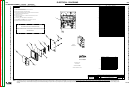
Located on the right
side of the control box.
Schematic M19752
TOROID
TOROID
TOROID
TOROID
TOROID
GND-C
567A
5
J83
niV+
J88
4.5 A PEAK
CURRENT
LIMIT
The contactor is
located behind
the glastic panel
next to the motor.
MICRO
CONTROLLER
Work
Located under the cover
in the control box ably.
Located behind the wire drive
Not a PC board; no schematic.
Access this connector
by removing the wire
drive asbly.
Located on the case
front. Remove the wire
drive asbly to gain
access.
Display
Board
Circuit
N.C.
Located on the lower left
of the front of the case.
N.A. CAVITY NUMBERING SEQUENCE AS VIEWED FROM COMPONENT SIDE OF BOARD.
N.B. CAVITY NUMBERING SEQUENCE AS VIEWED FROM LEAD SIDE OF CONNECTOR.
N.C. TOGGLE SWITCHES AND POTENTIOMETERS SHOWN FROM CONNECTION SIDE OF SWITCH.
+ 5V
COM
+ 15V
Located behind the insulating
wire drive panel. Remove the
wire drive ably to gain access.
Located under the cover at
the rear of the feeder
All LED’s light
briefly
Show CC/CV
mode and HI/LO
gear
Idle:
Display WFS, “---”
Wire Drive: OFF
Gas Solenoid: OFF
Enter Press and
Spin Mode
GAS PURGE SWITCH
DEPRESSED
GAS PURGE
SWITCH OFF
15-110 VDC from
welding power
source
526C
526B
ON/OFF
SWITCH
526
526B
587
589
587
589
2-STEP
TRIGGER
INTERLOCK
S2
554A
2 Step
2 Step
2 Step Trigger
15 VDC for 2 Step
0 VDC for Interlock
Interlock
Circuit
83% Procedure Input
0 VDC Normal
9 VDC 83% switch Closed
and Trigger Open
Trigger
15 VDC when Trigger and 83%
Switch Open
9 VDC when Trigger Open, 83%
Switch Closed
0 VDC when Trigger Closed
G-3
NOTE: This diagram is for reference only. It may not be accurate for all machines covered by this manual.