


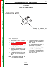

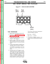
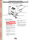

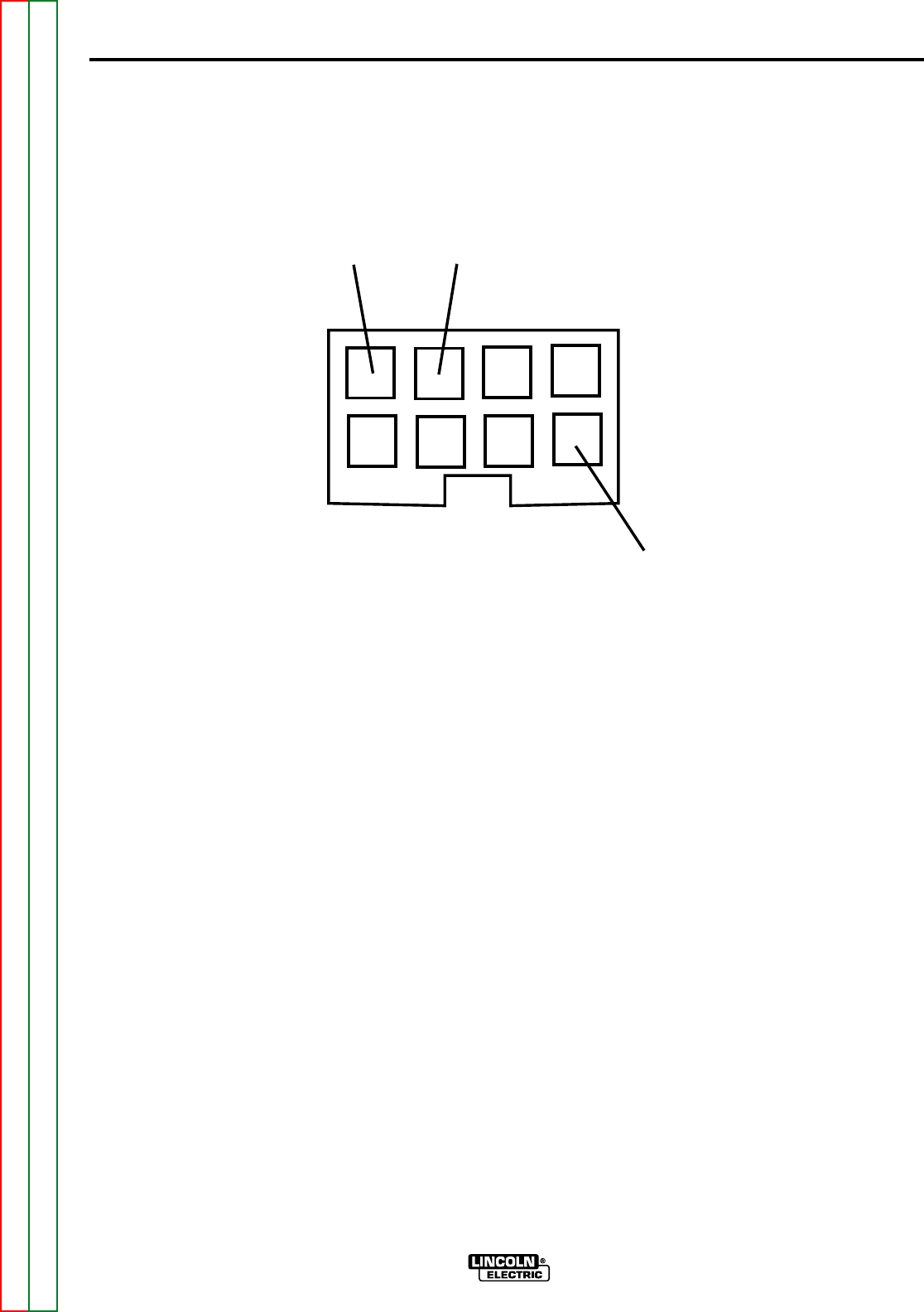
Blue
(562)
Red
(563)
Black
(561)
LN-15
F-22 F-22
Return to Section TOC Return to Section TOC Return to Section TOC Return to Section TOC
Return to Master TOC Return to Master TOC Return to Master TOC Return to Master TOC
TEST PROCEDURE
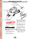
1. Remove the input power to the LN-15.
2. Perform the Wire Drive Assembly
Removal procedure.
3. Locate the three Hall Effect leads at
Plug J2. See Figure F7.
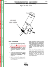
4. Apply at least 15VDC but no more
than 115VDC to the LN-15 from the
electrode cable to the work sensing
lead.
5. Check for the presence of 5VDC from
lead 563 (Red+) to lead 561 (Black-).
If the 5VDC is not present or low, the
feed head control board may be
faulty.
6. Activate the LN-15 trigger circuit,
make sure the drive motor is running
and check for the presence of
approximately 2.8VDC from lead 562
(Red+) to lead 561 (Black-). The
value of 2.8VDC represents the
correct feedback voltage from the Hall
Effect device to the control board.
This value can also be measured
using a frequency counter
50 in./min. = 120 HZ
700 in./min. = 1.6 KHZ
7. If the above voltage reading is not
correct, the Hall Effect device may be
faulty.
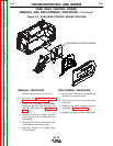
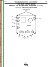
TROUBLESHOOTING AND REPAIR
HALL EFFECT MODULE TEST (Continued)
Figure F.7 - PLUG J2 LEAD LOCATION