


LN-15
F-36 F-36
Return to Section TOC Return to Section TOC Return to Section TOC Return to Section TOC
Return to Master TOC Return to Master TOC Return to Master TOC Return to Master TOC
TROUBLESHOOTING AND REPAIR
WIRE DRIVE ASSEMBLY
REMOVAL AND REPLACEMENT PROCEDURE (Continued)
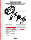
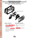
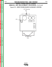
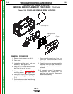
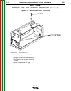
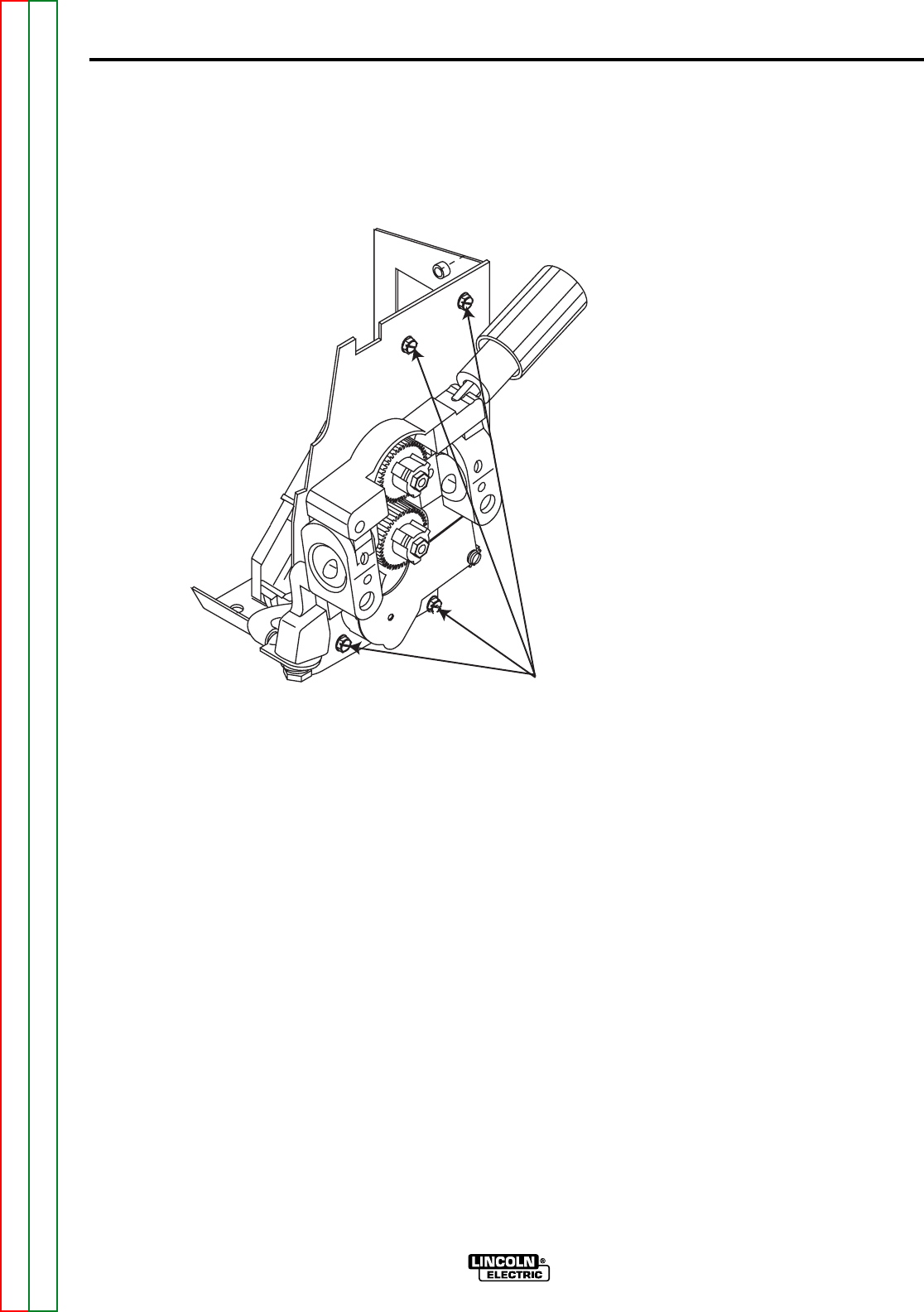
Figure F.13 - WIRE DRIVE MOUNTING SCREW LOCATION
REMOVAL PROCEDURE
1. Remove input power to the LN-15.
2. Open door.
3. Remove the four screws mounting the
wire drive assembly to the case. See
Figure F.13.
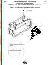
4. Using small pliers disconnect the gas
hose from the conductor block.
5. Carefully maneuver the drive assembly
out of the case.
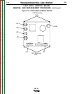
6. Using the 3/4” wrench remove the
cable from the conductor block.
7. Remove lead 67 from the conductor
block. See Wiring Diagram.
8. Remove plug J2.
REPLACEMENT PROCEDURE
1. Connect previously removed plug J2
to the new conductor block.
2. Replace lead 67 into the conductor
block.
3. Replace the cable onto the conductor
block.
4. Replace the gas hose onto the
conductor block.
5. Carefully maneuver the Wire Drive
Assembly into the case.
6. Secure assembly to machine using the
four previously removed screws.
MOUNTING SCREWS