


LN-15
INSTALLATION
A-6 A-6
Return to Section TOC Return to Section TOC Return to Section TOC Return to Section TOC
Return to Master TOC Return to Master TOC Return to Master TOC Return to Master TOC
GUN AND CABLE ASSEMBLIES
A variety of Lincoln 10' (3.0m) or 15' (4.6m) gun and
cable assemblies are available for use with the LN-15,
including the Magnum™ models for GMAW, K126 or
K115 models for Innershield®.
The LN-15 comes factory equipped with a K1500-2
gun connection kit, designed for guns having a
Magnum Tweco™ compatible #2-#4 connector. Many
other guns can easily be used with the LN-15 with
other K1500 series gun connection kits.
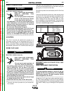
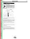
Gun Cable Connection to the Feeder
Lay the cable out straight. Insert the connector on the
welding conductor cable into the brass bushing on the
front of the wire drive unit. Keep the all mating surfaces
clean. Make sure it is fully seated and tighten the
thumb screw.
Connect the control cable plug into the 5 pin recepta-
cle on the front panel of the wire feeder.
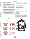
ELECTRODE POLARITY
The LN-15 automatically adjusts for positive and nega-
tive polarity. When welding with negative polarity pro-
cedures, the voltmeter will display a "-" sign; example
"-23.6" Volts.
CONNECTIONS
Across the Arc LN-15 models do not use a control
cable.
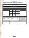
Table A.2 Trigger Connector J1 (5 Pin)
PIN Lead # Function
A 556 Trigger
B-Not used
C 554 Trigger/ 83%
Procedure ground
D 555 83% Procedure
E 554 Trigger/ 83%
Procedure ground
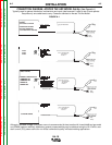
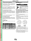
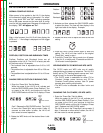
PROCEDURE TO INSTALL DRIVE ROLLS
AND WIRE GUIDES
• Turn off input power at the welding
power source before installation or
changing drive roll and/or wire
guides.
• Do not touch electrically live parts
0such as the wire drive or internal wiring.
• When feeding with the gun trigger, the electrode
and wire drive mechanism are "hot" to work and
ground and could remain energized several sec-
onds after the gun trigger is released.
• Only qualified personnel should perform this
operation.
------------------------------------------------------------------------
1. Turn OFF the welding power source.
2. Open the LN-15 case and then release the idle roll
pressure arm.
3. Remove the outer wire guide by turning the knurled
thumbscrews counter-clockwise to unscrew them
from the feed plate.
4. Rotate the triangular shaped drive roll retaining
mechanism to unlock the drive rolls and remove the
drive rolls.
5. Remove the inner wire guide.
6. Insert the new inner wire guide, groove side out,
over the two locating pins in the feed plate.
7. Install a drive roll on each hub assembly and lock by
rotating the triangular drive roll retaining mecha-
nism.
8. Install the outer wire guide by aligning it with the pins
and tightening the knurled thumbscrews.
9. Close the idle arm and engage the idle roll pressure
arm. Adjust the pressure appropriately.
WARNING