


LN-15
F-20 F-20
Return to Section TOC Return to Section TOC Return to Section TOC Return to Section TOC
Return to Master TOC Return to Master TOC Return to Master TOC Return to Master TOC
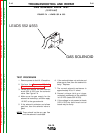
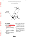
LEADS
550 & 551
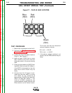
TEST PROCEDURE
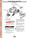
1. Remove the input power to the LN-15.
2. Perform the Wire Drive Assembly
Removal procedure.
3. Locate the Positive lead 550 (white)
and disconnect from motor. Note pin
location for reassembly. See Figure
F.6.
4. Locate the Negative lead 551 (gray)
and disconnect from motor. Note pin
location for reassembly. See
Figure F.6.
5. Apply a variable DC voltage to the
drive motor from lead 550(white)(+) to
lead 551(gray)(-).
6. When the supply voltage is varied
from 3 to 26 VDC, the drive motor
speed (RPM) should vary accordingly.
If the motor does not run or vary in
speed, the motor, gearbox or motor
brushes may be faulty. Check or
replace.
7. Check the resistance between each
of the motor leads and the motor
case. The resistance should be very
high (at least 500,000 ohms). If the
resistance is low, the motor is
grounded to the motor case and
should be replaced.
TROUBLESHOOTING AND REPAIR
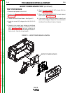
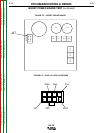
DRIVE MOTOR TEST (Continued)
Figure F.6- Motor Leads