


LN-15
.THEORY OF OPERATION
E-4 E-4
Return to Section TOC Return to Section TOC Return to Section TOC Return to Section TOC
Return to Master TOC Return to Master TOC Return to Master TOC Return to Master TOC
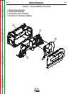
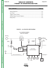
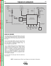
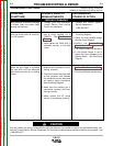
FIGURE E.4 – WIRE FEED SPEED CONTROL & FEEDBACK
CONTACTOR
ELECTRODE
INPUT VOLTAGE
TOROID
ASSEMBLY
FULL
WAVE
BRIDGE
WORK
SENSING
LEAD
ON/OFF
SWITCH
MOV
BOOST
POWER
SUPPLY
BOARD
FEED HEAD
BOARD SUPPLY
DRIVE MOTOR
SUPPLY
"WORK" VOLTAGE FEEDBACK #21
GAS
SOLENOID
"ELECTRODE"
FEEDBACK
VOLTAGE #67
FEED
PLATE
M
O
T
O
R
HALL
EFFECT
MODULE
RPM FEEDBACK
ARMATURE
WELDING
GUN
DISPLAY
BOARD
COLD
INCH
SWITCH
WIRE
FEED
SPEED
CONTROL
TRIGGER
INPUT &
PROCEDURE
TRIGGER
INTERLOCK
SWITCH
SPI COMMUNICATIONS
SHIELDED CABLE
FEED HEAD
CONTROL BOARD
WIRE FEED SPEED CONTROL AND
FEEDBACK
The combination of the Procedure Switch and the Wire
Feed Speed control provide a command voltage for
the Feed Head Control Board. The Hall Effect module
(Tach) monitors the motor RPM and outputs a digital
voltage frequency “feed back” that is delivered to the
Feed Head Board.
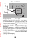
When operating in the constant voltage (CV) mode the
Feed Head Board monitors the feedback signal and
compares it to the command voltage and delivers the
appropriate armature voltage to the wire feed motor.
In this manner a constant wire feed speed is main-
tained.
When the LN-15 is connected to a constant current
(CC) power source a variable wire feed speed is desir-
able to compensate for the varying arc voltages asso-
ciated with the constant current process. To accom-
plish this the Feed Head Board monitors the command
voltage, the feed back signal from the Hall Effect mod-
ule and the arc voltage. These three factors are com-
pared and the appropriate armature voltage is applied
to the wire feed motor to compensate for the varying
arc lengths and associated arc voltages.
NOTE: Unshaded areas of Block Logic Diagram are the subject of discussion.