


THEORY OF OPERATION
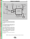
DISPLAY BOARD
The Display Board provides information to the user
through digital displays and LED’s. The Display Board
communicates with the Feed Head Board via the SPI
Bus cable.
The wire feed speed display shows the rate that the
LN-15 will feed wire during the welding process. The
wire feed speed is calibrated to within +/-2%. It
always displays the preset WFS.
The arc voltage display shows the average actual arc
voltage during the welding process. When welding
ceases the average arc voltage will continue to be
shown for 5 seconds. When not welding the display
show “----“. The voltage is calibrated to +/-2% over a
range of 10 to 45VDC. A negative “-“ will be automat-
ically displayed when the LN-15 is configured for elec-
trode negative processes.
All of the LEDs will briefly light when the machine is
first turned on.
E-5 E-5
Return to Section TOC Return to Section TOC Return to Section TOC Return to Section TOC
Return to Master TOC Return to Master TOC Return to Master TOC Return to Master TOC
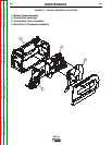
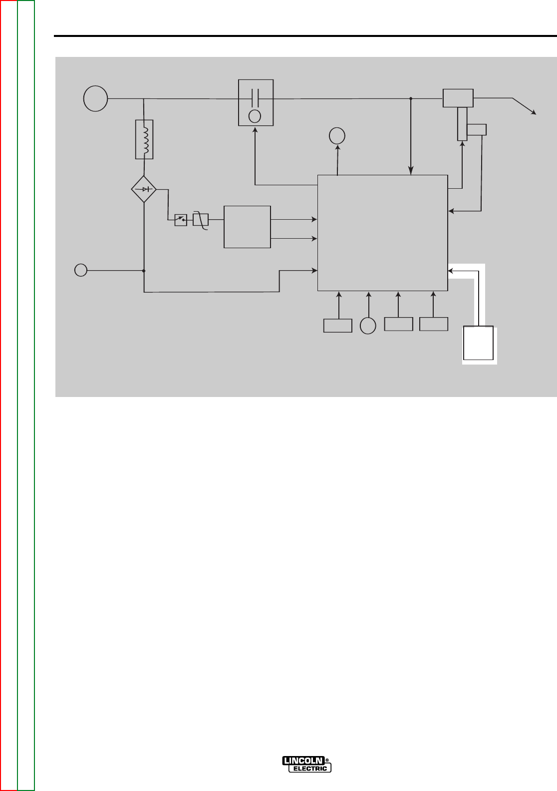
FIGURE E.5 – DISPLAY BOARD
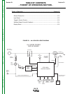
CONTACTOR
ELECTRODE
INPUT VOLTAGE
TOROID
ASSEMBLY
FULL
WAVE
BRIDGE
WORK
SENSING
LEAD
ON/OFF
SWITCH
MOV
BOOST
POWER
SUPPLY
BOARD
FEED HEAD
BOARD SUPPLY
DRIVE MOTOR
SUPPLY
"WORK" VOLTAGE FEEDBACK #21
GAS
SOLENOID
"ELECTRODE"
FEEDBACK
VOLTAGE #67
FEED
PLATE
M
O
T
O
R
HALL
EFFECT
MODULE
RPM FEEDBACK
ARMATURE
WELDING
GUN
DISPLAY
BOARD
COLD
INCH
SWITCH
WIRE
FEED
SPEED
CONTROL
TRIGGER
INPUT &
PROCEDURE
TRIGGER
INTERLOCK
SWITCH
SPI COMMUNICATIONS
SHIELDED CABLE
FEED HEAD
CONTROL BOARD
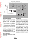
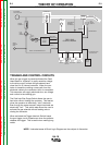
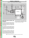
NOTE: Unshaded areas of Block Logic Diagram are the subject of discussion.
LN-15