


LN-15
F-38 F-38
Return to Section TOC Return to Section TOC Return to Section TOC Return to Section TOC
Return to Master TOC Return to Master TOC Return to Master TOC Return to Master TOC
TROUBLESHOOTING AND REPAIR
COVER AND SPINDLE MOUNT
REMOVAL AND REPLACEMENT PROCEDURE (Continued)
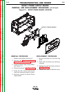
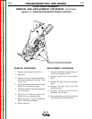
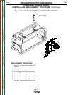
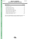
Figure F.14 - COVER AND SPINDLE MOUNT LOCATION
REMOVAL PROCEDURE
1. Remove input power to the LN-15.
2. Open door.
3. Locate the spindle mount and cover
assembly. See Figure F.14.
4. Using the 1/2” wrench remove the one
bolt from the top of the cover.
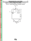
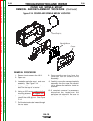
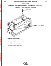
5. Using the 3/8” wrench remove the five
mounting screws. See Figure F.15.
6. Using the large pliers loosen and
remove the cord grip nut. See Figure
F.14.
7. Pull the electrode cable inward through
the rear case.
8. Disconnect the gas hose from the
conductor block on the Wire Drive
Assembly.
9. Carefully remove the cover and spindle
assembly from the case. Be careful
not to damage the switches, leads or
solenoid.
10. If complete removal is necessary
disconnect the leads from the
switches and solenoid. Be sure to
label for reassembly.
Cover
Spindle Mount
Cord Grip Nut