


LN-15
F-18 F-18
Return to Section TOC Return to Section TOC Return to Section TOC Return to Section TOC
Return to Master TOC Return to Master TOC Return to Master TOC Return to Master TOC
TROUBLESHOOTING AND REPAIR
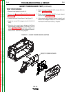
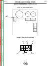
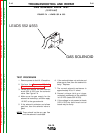
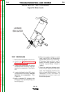
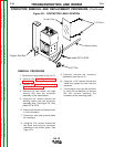
LARGE TERMINAL
STUDS
LEADS 507 & 578 (blue)
CONTACTOR TEST
(continued)
FIGURE F.5 – CONTACTOR
TEST PROCEDURE
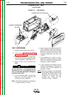
1. Remove input power to the LN-15.
2. Perform the Wire Drive Assembly
removal procedure.
3. Locate the contactor and leads 507
and 578 (blue) and separate the two
in line connectors. See Figure F.5.
4. Apply 12 VDC to the contactor coil
leads.
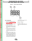
Do not leave the 12 VDC applied to the
contactor coil for a prolonged period of
time (15 seconds maximum). Damage to
contactor may result.
5. If the contactor does not activate
when the 12 VDC is applied, the
contactor is faulty. Replace.
Note: The normal contactor coil resistance
is approximately 4.4 ohms.
6. If the contactor activates when the 12
VDC is applied, check the resistance
between the two large terminal studs
with the contactor activated. The
resistance should be very low (0 to
1 ohm).
7. If the resistance is “high” or “open”
between the two large terminal studs
when the contactor is activated, the
contactor is faulty. Replace.
8. If the contactor activates and the
resistance between the terminals is
low when the 12 VDC is applied, the
contactor is good.
NOTE
: When the contactor is not activated,
the resistance between the terminals
should be very high (infinite). If the
resistance is always low, the
contacts are “stuck” and the
contactor is faulty. Replace.
CAUTION