


4 Connection
MITSUBISHI CNC
84
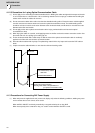
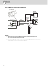
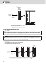
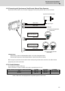
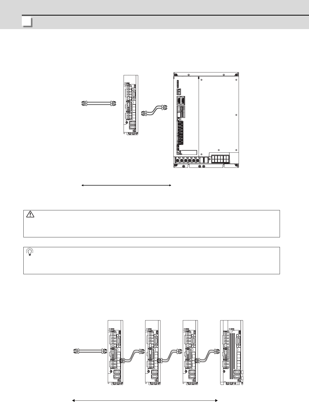
(2) When using the MDS-DJ unit together
4.2.5.2 Connecting with MDS-DJ Series
<Connection>
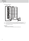
CN1A: CN1B connector on NC or previous stage's drive unit
CN1B: CN1A connector on next stage's drive unit
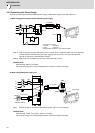
CAUTION
Connect the NC and the drive units by the optical communication cables. The distance between the NC and the
final drive unit must be within 30m and the bending radius within 80mm.
POINT
Axis Nos. are determined by the rotary switch for setting the axis No. (Refer to the MDS-DJ Series Instruction
Manual.) The axis No. has no relation to the order for connecting to the NC.
MDS-DM2-SPV
MDS-DJ-V1
Connected
to the NC
Optical
communication
cable
The optical communication cables from the NC to the
final drive unit must be within 30m.
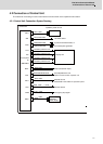
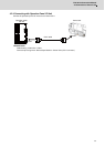
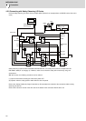
5th axis
(Final axis)
Servo:2nd/3rd/4th axis
Spindle:1st axis
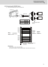
MDS-DJ-V1 MDS-DJ-SPMDS-DJ-V1 MDS-DJ-V1
3rd axis
4th axis
1st axis 2nd axis
Connected
to the NC
Optical
communication
cable
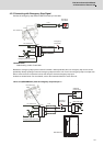
The optical communication cable up to 5m can be used in G396 series, up to 10m in G395 series, and up to 30m in G380 series.