


E70 Series Connection Manual
Appendix 1.1 Cable Wire and Assembly
117
Appendix 1.1 Cable Wire and Assembly
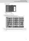
(1) Cable wire
The specifications of the wire used for each cable, and the machining methods are shown in this section. When
manufacturing the detector cable and battery connection cable, use the recommended wires shown below or equivalent
products.
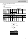
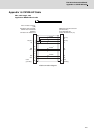
(a) Heat resistant specifications cable
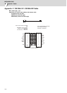
(b) General-purpose heat resistant specifications cable
(Note 1) Bando Electric Wire (Contact: +81-48-461-0561 http://www.bew.co.jp)
(Note 2) The Mitsubishi standard cable is the (a) Heat resistant specifications cable. For MDS-C1/CH series, (b) or
equivalent is used as the standard cable.
Core identification
Wire type
(special order part)
Finish
outer
diameter
Sheath
material
No. of
pairs
Wire characteristics
Configura
tion
Conductive
resistor
Withstand
voltage
Insulation
resistance
Heat
resistance
temperatu
re
Flexibility
BD20288
Compound 6-pair
shielded cable
Specification No.
Bangishi-17145
(Note 1)
8.7mm
Heat
resistant
PVC
2 (0.5mm
2
)
100
strands/
0.08mm
40.7Ω/km or
less
500VAC/
1min
1000MΩ/km
or more
105C°
70 × 10
4
times or
more at R200
4 (0.2mm
2
)
40
strands/
0.08mm
103Ω/km or
less
Wire type
(special order part)
Finish
outer
diameter
Sheath
material
No. of pairs
Wire characteristics
Configurat
ion
Conductive
resistor
Withstand
voltage
Insulation
resistance
Heat
resistance
temperatu
re
Flexibility
BD20032
Compound 6-pair
shielded cable
Specification No.
Bangishi-16903
Revision No. 3
(Note 1)
8.7mm PVC
2 (0.5mm
2
)
100
strands/
0.08mm
40.7Ω/km or
less
500VAC/
1min
1000MΩ/
km or more
60C°
100 × 10
4
times or
more at R200
4 (0.2mm
2
)
40
strands/
0.08mm
103Ω/km or
less
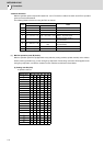
Pair No.
Insulator color
L1 L2
A1 (0.5mm
2
)
Red White
A2 (0.5mm
2
)
Black White
B1 (0.2mm
2
)
Brown Orange
B2 (0.2mm
2
)
Blue Green
B3 (0.2mm
2
)
Purple White
B4 (0.2mm
2
)
Yellow White
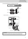
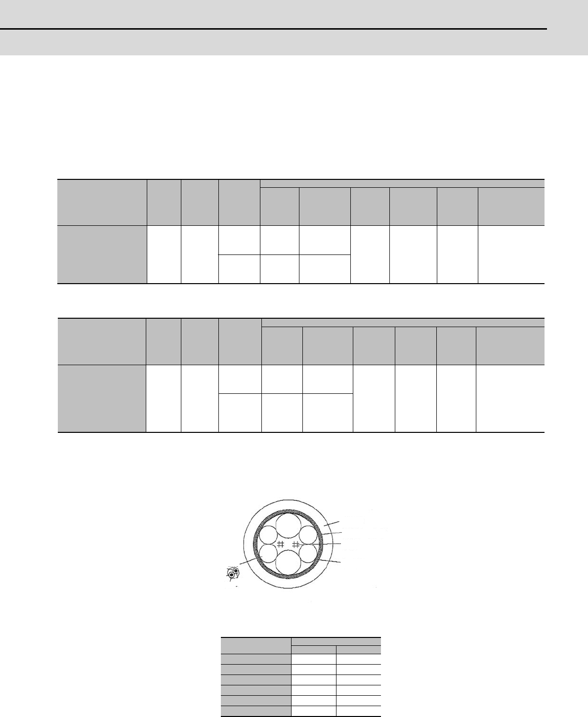
Sheath
Mesh shield
Intervening wire
Tape
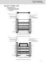
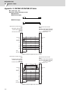
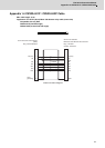
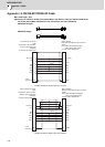
Compound 6-pair cable structure drawing
Cable core
Insulator
Conductor