


1 System Configuration
MITSUBISHI CNC
4
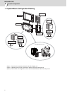
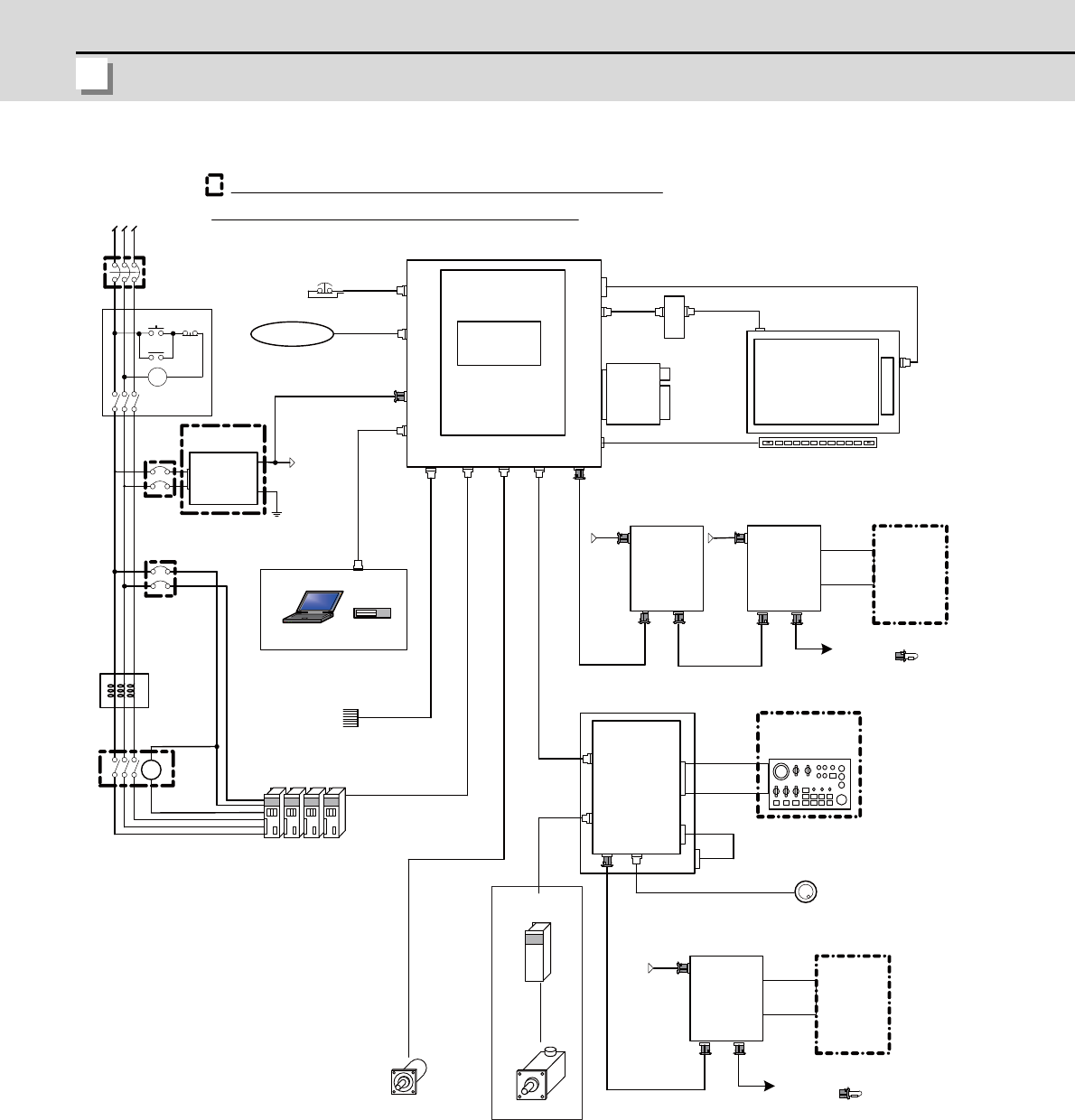
[Analog Spindle Configuration]
(Note 1) For information on how to connect the drive unit, refer to the drive unit's manual.
(Note 2) For a connection of the MITSUBISHI CNC Machine Operation Panel, refer to "Connection: Connection of
MITSUBISHI CNC Machine Operation Panel" to be described.
L1 L2 L3
MC
ON OFF
MC
MC
EMG
F120
G300/G301
F070
FG
DCOUT
FG
ACIN
DC24V
CP/NFB
CP/NFB
D-AL
MC
FCU7-KB0xx
RIO2
EMG
SIO
NCKB
LCD
LED driver : HN281
1ch:F034
Sensorsignals
Max.8points
LAN
CG3x
(VGA:640×480)
RIO1
OPT
FRONT
FCU7-DX621/721
DCIN
FCUA-DX1x1
RIO1SKIP ENC
USER 2ch
2ch
1ch
INV
12V:F320/F321
5V:F023/F024
FCUA-R030
G395/G396/G380
FCUA-R050/054
FCU7-DU120-13
G011
RIO2RIO1
DCIN
FCUA-DX1x1
CG71
DC24V DC24V
MENUKEY
2ch:F035
1ch
FCUA-R211
/SH41
CG71
HN441
max.0.5m
<G402>
RIO3 MPG
DI-L/R
RIO2RIO1
DCIN
FCUA-DX1x1
DC24V
FCUA-R211
/SH41
FCUA-R211
/SH41
F351
DI-L/R
FCUA-
R300
/R301
FCUA-
R300
/R301
F070
F070
F070
<G487>
DCIN
HN793
CF card I/F
<G497>
FCU7-MU558
<G488>
AO
F221
max.30m
OSE1024
max.30m
USB
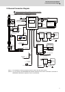
Remote I/O unit
To the next remote I/O
or terminator
Machine
control relay/
contact
Manual pulse generator
Machine operation
panel made by
machine tool builder
Keyboard unit
Operation panel I/O unit
Skip signal input
Drive units
AC reactor
Contactor
24VDC stabilized
power supply
Circuit protector (CP)
The name with brackets < > indicates the cable for the unit.
No-fuse breaker (NFB)
Dotted lines indicate the sections prepared by the machine tool builder.
CNC control unit
Main card HN768
Memory card
Front
memory
I/F card
Display unit
Menu keys
To the next remote I/O
or terminator
Machine
control relay/
contact
Spindle motor
Synchronous feed encoder
RS232C device
Ethernet device