


December 2002 TOSHIBA TEC 1 - 91 e-STUDIO160/200/250 ADJUSTMENT ITEMS
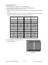
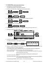
10. Entering the adjustment value for the printing position.
Enter the setting value for the following 21 items.
For the setting values, refer to the FUNCTION LIST printed before replacing the MAIN PWA, or the
FUNCTION LIST on the inside of the rear cover of the copier.
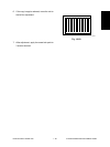
When the FUNCTION LIST is not printed in 08-404/401/251/252, perform the following setting.
08-404: Enter the remainder obtained by dividing the total counter value (08-351) by the process
unit life value (27k or 33k).
08-401: Find a remainder by dividing the total counter value (08-351) by the process life unit value
(27k or 33k).
Enter the value obtained by multiplying the remainder by 4.7 (for e-STUDIO160/200 series)
or 4.5 (for e-STUDIO250 series).
08-251: When it was set before the MAIN PWA was replaced, perform the setting again.
08-252: Enter the remainder obtained by dividing the total counter value (08-351) by the PM life
value (81k or 99k).
When 08-251 is “0,” however, it is not necessary to enter the 08-252 value.
For the setting procedures, refer to sections 1.2.1 and 1.2.2 of the Service Handbook.
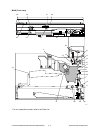
1: 05-205 (Developer bias DC adjustment)
2: 05-210 (Grid voltage initial value adjustment)
3: 05-220 Transfer H
4: 05-221 Transfer C
5: 05-233 Separation H
6: 05-234 Separation C
7: 05-235 Separation L
8: 05-400 (Printer primary scanning reproduction ratio)
9: 05-410 (Laser start position)
10: 05-421 (Printer secondary scanning reproduction ratio)
11: 05-440 (Leading edge)
12: 05-430 (Top margin)
13: 05-431 (Left margin)
14: 05-432 (Right margin)
15: 05-433 (Bottom margin)
16: 08-404 (Developer material counter)
17: 08-401 (Drum life counter)
18: 08-251 (PM counter setting value)
19: 08-252 (PM counter present value)
20: 08-446 Transfer ON position
21: 08-447 Transfer OFF position
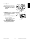
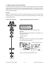
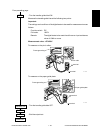
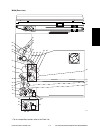
11. Sensor test in the [1] [3] test mode.
1: Confirm whether the attached options are reflected on the bit information correctly.
2: Refer to 1.2.4 of the Service Handbook.
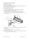
12. SRAM test/DRAM test/Clock IC test/CODEC test mode.
For details, see chapter 8 of the Operator’s Manual.