


Battery Information
B–12 975-0012-01-02 Rev A
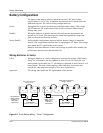
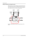
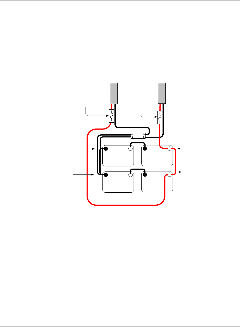
Battery Connections for Stacked Inverters
When using inverters in a stacked configuration, the same battery bank must be
used for both inverters. To ensure even charging of the batteries, each inverter
must be connected to both strings (i.e., positive cable to string two, and negative
cable to string one for inverter 1, and positive cable to string one and negative
cable to string two for inverter 2) as shown in the diagram below.
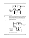
Figure B-7
Example of Battery Connections for Stacked Inverters (24 Vdc
shown)
DC CONDUIT
FOR
INVERTER 1
(Primary)
– +
12 Volt
Battery
200 Ah
– +
12 Volt
Battery
200 Ah
+–
12 Volt
Battery
200 Ah
Series String 1
Series String 2
DC CONDUIT
FOR
INVERTER 2
(Secondary)
24 VDC/200 Ah
24 VDC/200 Ah
– +
12 Volt
Battery
200 Ah
Shunt
Batteries in
Parallel
24 VDC 400 Ah
DC Disconnect
(either a circuit
breaker or a
fuse with a
disconnect)
DC Disconnect
(either a circuit
breaker or a
fuse with a
disconnect)