


DC Wiring
975-0012-01-02 Rev A 2–19
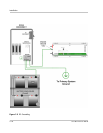
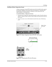
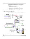
Connecting the Battery Bank to the Inverter
Follow the procedure below to connect the battery bank to the inverter.
To connect the battery bank to the inverter:
1. Determine the correct size battery cable to use for installation from Table 2-3
on page 2–16.
2. Determine the correct size disconnect/fuse for installation from Table 2-4 on
page 2–17.
3. Color code the cables with tape or heat shrink tubing. The standard colors are
red for positive (+) and black for negative (–). (NEC requires white for the
negative conductors.)
4. Connect the negative (–) cable to the battery’s negative terminal (torque to
manufacturer’s recommendations).
5. Install the over-current device (fuse or circuit breaker) between the battery’s
positive terminal and the inverter’s positive terminal (as close to the batteries
as possible).
6. Connect the (short) positive cable to the battery’s positive terminal (torque to
manufacturer’s recommendations).
7. Ensure the correct polarity of the cables with a DC voltmeter (DVM).
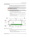
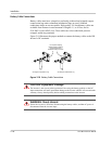
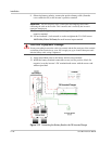
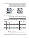
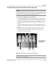
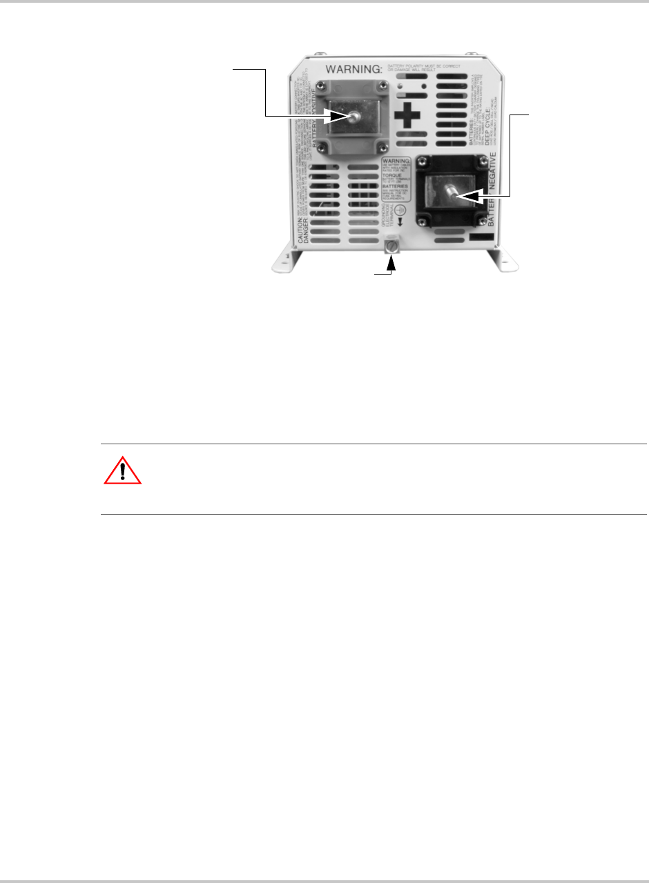
Figure 2-11
DC Terminals on the DR Inverter
Ground Lug
Negative (–)
Battery Terminal
Positive (+)
Battery Terminal
Torque the
Positive (+)
Battery terminal to
10-15 ft-lbs
(13.6 to 20.3 nm)
Torque value for
the Ground Lug
is 10-15 in-lbs
(1.1 to 1.7 nm)
Torque the
Negative (–)
Battery terminal to
10-15 ft-lbs
(13.6 to 20.3 nm)
:
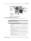
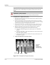
WARNING: Shock Hazard
Ensure the inverter is off before connecting or disconnecting the battery cables and that all
AC power is disconnected from the inverter’s inputs.