


Installation
2–4 975-0012-01-02 Rev A
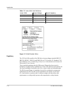
Hardware / Materials Required
The following hardware or materials may be required to complete this installation.
❐ 4 ft. x 4 ft. sheet of 3/4" plywood or 2 x 4’s studding material
❐ #12 wood screws (or 1/2" x 1-1/4" lag bolts)
❐ Conduit and appropriate fittings
❐ Wire nuts
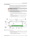
Wiring Considerations
All wiring and installation methods should conform to applicable electrical and
building codes.
Pre-plan the wire and conduit runs.
• The AC terminals accept cable sizes up to #6 AWG.
• The DC terminals accept cable sizes up to #4/0 AWG that use ring terminals
with 5/16" holes.
For maximum safety, run both AC and DC cables in conduit.
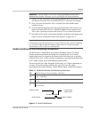
DC Terminal Connections
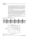
Battery-to-inverter cabling should be only as long as required.
For Example: If #4/0 AWG cables are used, do not exceed 5 feet (one way) in
12 Vdc systems; do not exceed 10 feet (one way) in 24 Vdc systems.
For optimum performance, use pre-assembled battery cables designed specifically
for this application (available from Xantrex).
Grounding Considerations
AC Grounding
The inverter/charger should be connected to a grounded, permanent wiring
system. Neutral and ground conductors should only be bonded at the main
electrical service panel.
DC Grounding
The negative battery conductor should be bonded to the grounding system at only
one point in the system. The size for the conductor is usually based on the size of
the largest conductor in the DC system.