


Multi-wire Branch Circuit Wiring
C–2 975-0012-01-02 Rev A
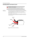
Multi-wire Branch Circuits
Problem A potential safety problem exists when installing stand-alone 120 Vac inverters
into existing 120/240 Vac wired panels where multi-wire branch circuit wiring
methods were used.
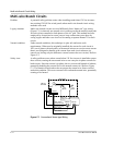
Legacy situation Multi-wire branch circuits are wired differently from “home run” type wiring
(Figure C-1) in that only one neutral wire is used to provide the neutral-return path
for each circuit connected to both phases of the AC grid. This method has been
employed by electricians in recent years to keep construction costs down by
saving copper and labor costs involved in running a separate Romex™ for each
circuit.
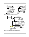
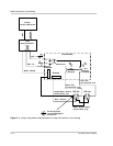
Normal condition Under normal conditions, this technique is quite safe and meets code
requirements. When used as originally installed, the current for each circuit is
180° out-of-phase with each other, so the neutral wire never receives more current
than it was designed to handle as the current from each circuit subtracts (or
cancels out, leaving only the difference current between the two circuits). Refer to
Figure C-2.
Safety issue A safety problem occurs when a stand-alone 120 Vac inverter is installed to power
these circuits, causing the one neutral wire to now carry the in-phase currents for
both circuits. Since the current is in-phase, the two circuits add instead of subtract,
potentially doubling the current flow in the neutral return wire! Refer to Figure
C-3. The branch circuit breakers do not protect the neutral wire from overload
under this condition. This excess current will overheat the neutral wire, potentially
creating a fire hazard.
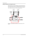
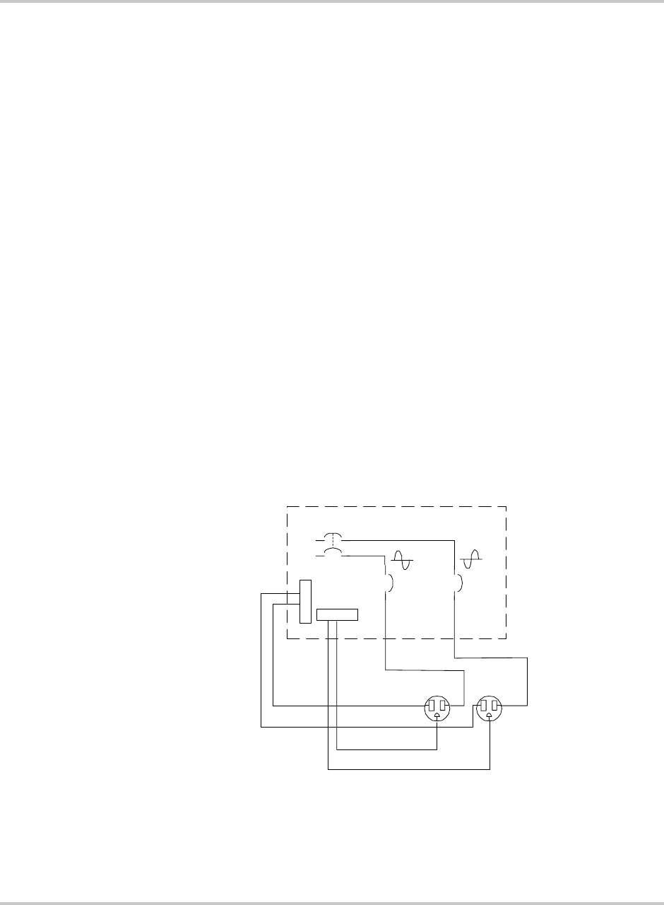
Figure C-1
Conventional Home-type Wiring
Load Center
L1
L2
Neutral
Ground
120 Vac
15 A
Breaker
15 A
Breaker
240 Vac
from Grid
Bare - Ground
White - Neutral
(Current Flow 15 A)
Black - Hot
(Current Flow 15A)
120 Vac
Black - Hot
(Current Flow 15A)
White - Neutral
(Current Flow 15 A)
Bare - Ground