


DC Wiring
975-0012-01-02 Rev A 2–13
DC Wiring
This section describes the DC wiring requirements and how to make the
connections. It provides the required cable and wire sizes, recommended lengths
for cables, and disconnect/circuit breaker requirements.
DC Circuit Grounding
Grounding is an important part of the system installation and must be performed
correctly to ensure safe operation of the equipment. Grounding requirements vary
by country and application. Consult the NEC for specific requirements.
The ground conductor should be sized appropriately for the over-current
protection device being used and according to NEC 250-95 (Ninth Edition)
(see Table 2-2 below for a portion of the NEC code).
General DC Grounding Requirements
This product is intended to be installed as part of a permanently grounded
electrical system per the National Electric Code ANSI/NFPA 70 (current edition).
This is the single point earth ground for the inverter system.
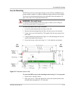
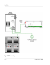
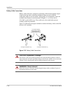
To ground the DC circuits:
1. Connect the negative (-) terminal of the battery bank to an appropriately sized
conductor and connect it to the ground bus in the DC Disconnect.
2. Connect an appropriately sized conductor to the Ground bus in the DC
Disconnect and connect it to the primary system ground.
The system ground is the same ground used by the AC side of the system.
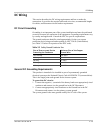
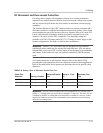
Table 2-2
Safety Ground Conductor Size
Size of Over-current Device
Protecting the Conductor
Minimum Size of the Copper
Ground Wire
30 or 60 amp #10 AWG
100 amp #8 AWG
200 amp #6 AWG
300 amp #4 AWG
400 amp #3 AWG