


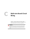

Multi-wire Branch Circuits
975-0012-01-02 Rev A C–3
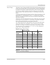
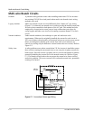
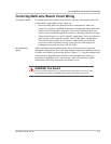
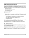
Figure C-2
Multi-wire Branch Circuit Wiring and Current Flow
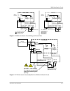
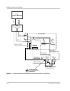
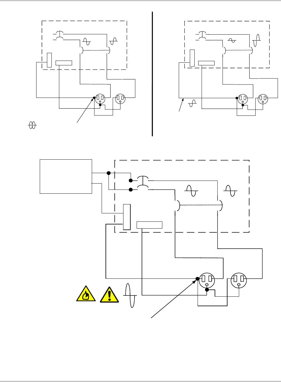
Figure C-3
120 Vac Inverter Incorrectly Wired in a Multi-wire Branch Circuit
Load Center
L1
L2
Neutral
Ground
120 Vac
120 Vac
15 A
Breaker
(Ganged)
240 Vac
f
rom Grid
Bare - Ground
Single White - Neutral
(Current Flow 0 A)
Black - Hot
(Current Flow 15 A)
Red - Hot
(Current Flow 15 A)
Bare - Ground Splice
White - Neutral Splice
(Current Flow 15 A)
Out-of-Phase current
subtract at this point
(Current Flow 0 A)
15 A
Breaker
(Ganged)
Load Center
L1
L2
Neutral
Ground
120 Vac 120 Vac
15 A
Breaker
(Ganged)
240 Vac
from Grid
Bare - Ground
Single White - Neutral
(Current Flow 10 A)
Black - Hot
(Current Flow 5 A)
Red - Hot
(Current Flow 15 A)
White - Neutral Splice
(Current Flow 15 A)
When unbalanced
current flows through
each leg, only the
difference current
flows through the
neutral return wire.
15 A
Breaker
(Ganged)
Load Center
L1
L2
Neutral
Ground
120 Vac 120 Vac
15 A
Breaker
(Ganged)
Bare - Ground
Single White - Neutral
(Current Flow 30 A)
Black - Hot
(Current Flow 15 A)
Red - Hot
(Current Flow 15 A
White - Neutral Splice
(Current Flow 15 A)
WARNING: FIRE HAZARD
The in-phase currents ADDS
at this point exceeding wire
capacity!
15 A
Breaker
(Ganged)
120 Vac
Inverter or Generator