


Operation
3–4 975-0012-01-02 Rev A
• Erratic Blinking (0 to 3 and 2 to 5 flashes @ 2 second intervals) - The
inverter has detected an error condition caused by overheating, low battery
voltage, or high battery voltage.
• OFF - The inverter is OFF.
The remote control must be connected prior to switching the inverter ON;
otherwise, the micro-controller will not recognize (or respond to) the remote. If
the remote is not recognized, switch the inverter OFF and then ON using the
inverter’s front panel POWER ON/OFF switch.
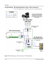
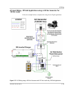
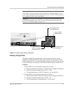
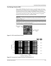
Stacking Interface
Whenever two DR Series inverters are used in a series (stacked) configuration,
one unit (primary) controls the other unit (secondary). Communication between
the two inverters is done via the COM port (J1). The first unit switched ON, using
its front panel POWER ON/OFF switch, becomes the controlling (primary)
inverter.
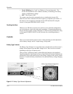
Controls
There are several controls on the inverter’s front panel that provide adjustments
for the battery charger, and AC output energy saving mode.
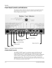
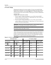
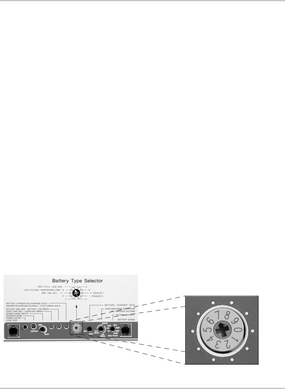
Battery Type Selector
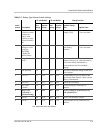
The Battery Type Selector is a 10 position rotary switch used to set the inverter’s
charger for the proper Float and Bulk voltage levels. These levels are selected
depending on the type of batteries used.
There are also 2 positions (0 and 1) which allow the batteries to be equalized.
Equalizing batteries should only be done on liquid lead acid batteries and never on
gel batteries. Refer to the table below for the charge voltages in the various switch
positions. Consult the battery manufacturer for optimum battery voltage charging
settings.
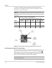
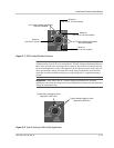
Figure 3-2
Battery Type Selector Adjustment
Battery Type Selector Enlargement
(pointing to Setting 7)