


Operation
3–2 975-0012-01-02 Rev A
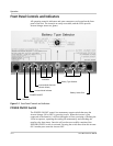
Front Panel Controls and Indicators
All operating controls, indicators and sense connectors are located on the front
panel of the unit. The controls are easily accessible, and the LEDs provide
inverter/charger status at a glance.
POWER ON/OFF Switch
The POWER ON/OFF control is a momentary contact switch that turns the
inverter/charger ON or OFF by pressing it once. When the inverter is first
connected to the batteries, it will run through a self test consisting of flashing the
LEDs in sequence, operating the cooling fan momentarily and switching the
transfer relay three times. Once the self test has successfully completed, the
POWER ON/OFF switch is activated. Pressing the switch once turns the inverter
ON. Another press turns the inverter OFF.
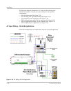
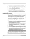
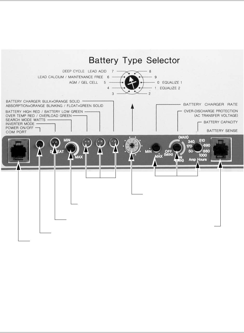
Figure 3-1
Front Panel Controls and Indicators
COM Port
Battery Sense Port
POWER ON/OFF
Inverter Mode Controls
(Search Watts)
Inverter Mode Indicator
Battery Type Selector
Battery Charge Control
LED Status
Indicators