


975-0012-01-02 Rev A xiii
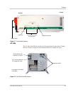
Figure 1-1 Front Panel Features - - - - - - - - - - - - - - - - - - - - - - - - - - - - - - - - - - - - - - - - - - - - - - 1–3
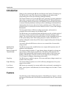
Figure 1-2 AC Side of the DR Inverter- - - - - - - - - - - - - - - - - - - - - - - - - - - - - - - - - - - - - - - - - - 1–3
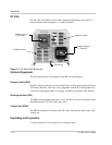
Figure 1-3 DC Side of the DR Inverter- - - - - - - - - - - - - - - - - - - - - - - - - - - - - - - - - - - - - - - - - - 1–4
Figure 1-4 Product Identification - - - - - - - - - - - - - - - - - - - - - - - - - - - - - - - - - - - - - - - - - - - - - 1–5
Figure 1-5 Model/Serial Number Sticker - - - - - - - - - - - - - - - - - - - - - - - - - - - - - - - - - - - - - - - - 1–6
Figure 2-1 On-Grid Basic Configuration (Utility Backup)- - - - - - - - - - - - - - - - - - - - - - - - - - - - - 2–7
Figure 2-2 Off-Grid Configuration (Generator only) - - - - - - - - - - - - - - - - - - - - - - - - - - - - - - - - 2–7
Figure 2-3 On-Grid Configuration - with Renewable Energy Sources - - - - - - - - - - - - - - - - - - - - - 2–8
Figure 2-4 Off-Grid Configuration - with Renewable Energy Sources- - - - - - - - - - - - - - - - - - - - - 2–9
Figure 2-5 Charge Rate versus Peak AC Voltage- - - - - - - - - - - - - - - - - - - - - - - - - - - - - - - - - - 2–10
Figure 2-6 Dimensions (not to scale) - - - - - - - - - - - - - - - - - - - - - - - - - - - - - - - - - - - - - - - - - - 2–11
Figure 2-7 Suggested Mounting Method - - - - - - - - - - - - - - - - - - - - - - - - - - - - - - - - - - - - - - - 2–12
Figure 2-8 Mounting on Plywood - - - - - - - - - - - - - - - - - - - - - - - - - - - - - - - - - - - - - - - - - - - - 2–12
Figure 2-9 DC Grounding - - - - - - - - - - - - - - - - - - - - - - - - - - - - - - - - - - - - - - - - - - - - - - - - - 2–14
Figure 2-10 Battery Cable Connections - - - - - - - - - - - - - - - - - - - - - - - - - - - - - - - - - - - - - - - - - 2–18
Figure 2-11 DC Terminals on the DR Inverter - - - - - - - - - - - - - - - - - - - - - - - - - - - - - - - - - - - - 2–19
Figure 2-12 Connecting the Battery Bank to the DR Inverter/Charger- - - - - - - - - - - - - - - - - - - - - 2–20
Figure 2-13 Battery Temperature Sensor (BTS) RJ11 Jack Location - - - - - - - - - - - - - - - - - - - - - 2–21
Figure 2-14 Connecting the BTS to the DR Inverter - - - - - - - - - - - - - - - - - - - - - - - - - - - - - - - - 2–21
Figure 2-15 AC Side Cover Panels - - - - - - - - - - - - - - - - - - - - - - - - - - - - - - - - - - - - - - - - - - - - 2–23
Figure 2-16 AC Terminals for AC Input to the Inverter - - - - - - - - - - - - - - - - - - - - - - - - - - - - - - 2–24
Figure 2-17 AC Terminals for AC output to the Sub-panel - - - - - - - - - - - - - - - - - - - - - - - - - - - - 2–25
Figure 2-18 AC Wiring- On-Grid Application - - - - - - - - - - - - - - - - - - - - - - - - - - - - - - - - - - - - 2–26
Figure 2-19 AC Wiring using a Generator - On-Grid Application - - - - - - - - - - - - - - - - - - - - - - - 2–27
Figure 2-20 AC Wiring using a 120 Vac Generator - Off-Grid Application - - - - - - - - - - - - - - - - - 2–28
Figure 2-21 AC Wiring using a 240 Vac Generator with 120 Vac Loads only- Off-Grid Application2–29
Figure 2-22 AC Wiring for dual-inverters - On-Grid Application (120 Vac models only) - - - - - - - 2–31
Figure 2-23 Wiring for dual-inverters - On-Grid Application (120 Vac models only) - - - - - - - - - - 2–32
Figure 3-1 Front Panel Controls and Indicators - - - - - - - - - - - - - - - - - - - - - - - - - - - - - - - - - - - - 3–2
Figure 3-2 Battery Type Selector Adjustment - - - - - - - - - - - - - - - - - - - - - - - - - - - - - - - - - - - - - 3–4
Figure 3-3 Battery Type Selector Adjustment - - - - - - - - - - - - - - - - - - - - - - - - - - - - - - - - - - - - - 3–7
Figure 3-4 Battery Charger Rate Potentiometer (DR1512 values used) - - - - - - - - - - - - - - - - - - - - 3–8
Figure 3-5 ODP Enabled/Disabled Positions- - - - - - - - - - - - - - - - - - - - - - - - - - - - - - - - - - - - - - 3–9
Figure 3-6 Automatically Calculated Discharge Cutoff Voltage per Cell - - - - - - - - - - - - - - - - - - - 3–9
Figure 3-7 ODP Enabled/Disabled Positions- - - - - - - - - - - - - - - - - - - - - - - - - - - - - - - - - - - - - 3–11
Figure 3-8 Typical Setting for Most Utility Application - - - - - - - - - - - - - - - - - - - - - - - - - - - - - 3–11
Figures