


Installation
2–22 975-0012-01-02 Rev A
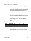
AC Wiring
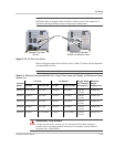
This section describes the AC wiring requirements and how to make the
connections. It provides the required wire sizes, recommended lengths for
conductors, and disconnect/circuit breaker requirements.
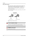
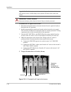
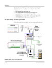
AC Distribution Panel (Sub-panel) Mounting and Conduit Installation
1. Determine the location of the sub-panel and install it according to the
manufacturer’s directions.
2. Install the AC conduit between the sub-panel (output) and inverter.
3. Install conduit between the inverter (input) and the main breaker box.
4. Determine which circuits require backup. Install the appropriate circuit
breakers into the sub-panel.
5. Install an appropriately sized circuit breaker (30 amp maximum) in the
sub-panel. This will later be wired to the inverter’s output. If two inverters are
being used in a stacked configuration, install a double-pole circuit breaker for
240 Vac service.
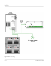
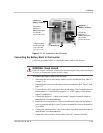
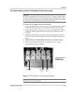
Accessing the AC Terminals
All AC wiring connects to the terminal block located on the right-hand side of the
inverter.
To make the AC connections to the inverter:
1. To access the terminal block, remove the side cover panels (if installed) by
removing the two (or three) Phillips screws. Units are shipped without the
covers installed (packed in a small plastic bag with additional hardware).
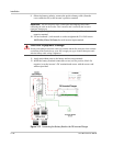
2. Locate the AC input and output terminals on the block. Refer to Figure 2-15
on page 2–23.
Important:
The installation of sub-panels and wiring should be performed by a
qualified person or a licensed electrician following all local and NEC codes.
WARNING: Shock Hazard
Disconnect the power from the utility’s main breaker box before proceeding.
CAUTION: Equipment Damage
The inverter’s AC output must never be wired to the utility or generator output. This will
cause severe damage to the inverter which is not covered under warranty.