


Front Panel Controls and Indicators
975-0012-01-02 Rev A 3–13
LED Indicators
There are four LEDs on the inverter’s front panel, indicating inverter status,
battery condition, over temperature/overload conditions and charger status. These
LEDs blink or change color depending on the condition or function they are
displaying.
Inverter Mode LED - Green
The green Inverter Mode LED lights (solid) to indicate the inverter is running on
batteries (full wave operation). When the inverter is in search mode (no load
applied) the LED flashes 2 to 3 times per second. During AC line operation, with
AC passing directly through to the connected load, the LED remains OFF.
Over Temp / Overload LED - Red / Green (error condition)
The Over Temp / Overload LED is a dual color, dual function indicator. When the
inverter’s temperature is too high for safe operation, the LED lights (red) to
indicate the Over Temp condition. When the temperature returns to a safe level,
the LED turns OFF. If the condition persists, the inverter will shut down, cool and
then restart.
Whenever the current draw exceeds a value programmed into the micro-
controller, the LED lights (green) to indicate the Overload condition. The LED
can remain ON for up to one hour (before inverter shutdown) if the condition is
caused by a fault in the charger circuit. When the fault condition clears, the LED
turns OFF. If the condition is caused by backfeed (connecting the AC line to the
inverter’s output) the LED will remain ON for approximately 10 seconds before
the inverter shuts down.
Battery High/Battery Low LED - Red/Green (error condition)
The Battery Hi / Battery Low LED is a dual-color, dual-function indicator.
Whenever battery voltage exceeds a safe value, the LED lights red to indicate the
condition. This value is typically 15.5 volts DC for a 12 volt system (31 volts DC
for a 24 volt system). If the condition persists, the inverter will shut down until the
battery voltage returns to a safe level and then restart.
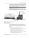
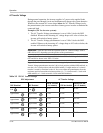
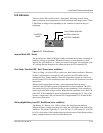
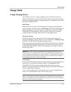
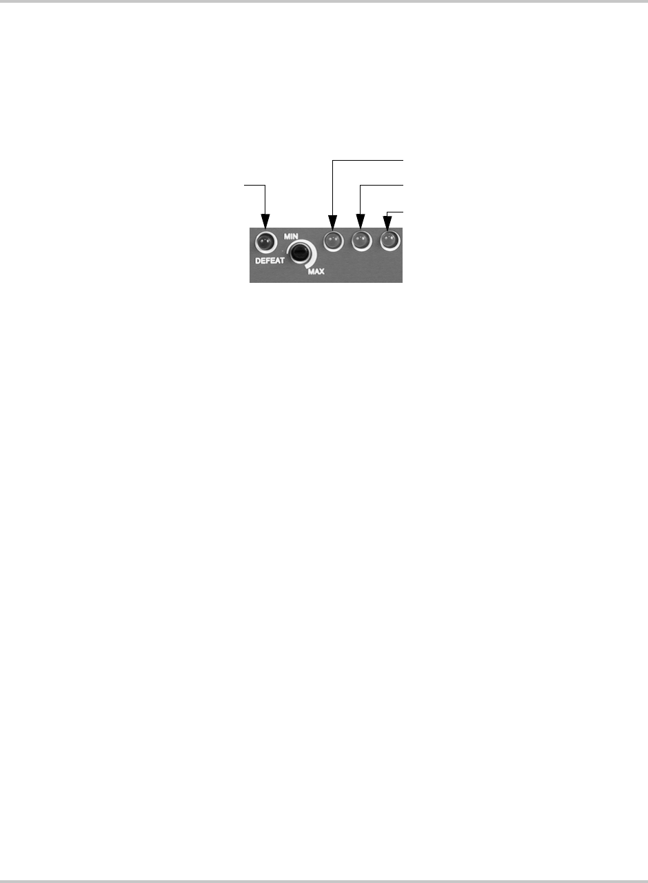
Figure 3-11
LED Indicators
INVERTER
MODE
OVER TEMP/OVERLOAD
BATTERY HIGH/LOW
BATTERY CHARGER