


Operation
3–8 975-0012-01-02 Rev A
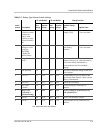
Use Table 3-2 to find the approximate setting of the Battery Charge Rate
potentiometer. The settings do not need to be exact, but should be as close as
possible to the actual value required.
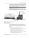
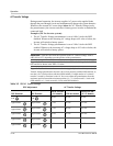
Over Discharge Protection/AC Transfer Voltage
The Over Discharge Protection/AC Transfer Voltage potentiometer performs two
related functions. When set between the 2 and 5 o’clock position (right), both
ODP and the AC Transfer Voltage function simultaneously (see table on next
page). When the potentiometer is set between the 9 and 1 o’clock position (left),
only the AC Transfer Voltage is functional (ODP is disabled).
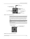
Important:
The potentiometer does not have an arrow to indicate its position. Use a
small blade screwdriver and rotate the control completely CCW to find the start position.
Rotate the potentiometer CW to the desired position (i.e., halfway between the stops for a
50% setting).
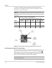
Table 3-2
Approximate Charge rate Setting/Amperage
Model
Percent of Potentiometer Rotation (between stops)
0% Min. 25% 50% 75%
100%
Max
DR1512
DR2424
DR3624
0 amps 17.5 amps 35 amps 52.5 amps 70 amps
DR2412 0 amps 30 amps 60 amps 90 amps 120 amps
DR1524 0 amps 8.75 amps 17.5 amps 26.25 amps 35 amps
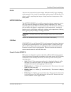
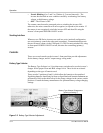
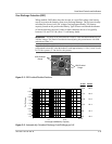
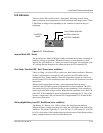
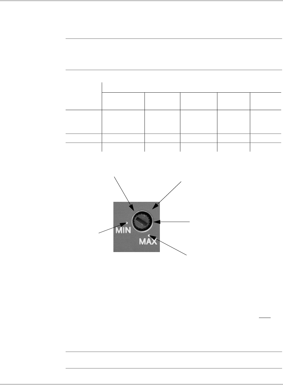
Figure 3-4
Battery Charger Rate Potentiometer (DR1512 values used)
0%
(0 amps
100%
(70 amps)
Example 1
50%
(35 amps
75%
(50 amps)
Example 2
25%
(17.5 amps
Important:
The ODP is not scaled. It is either on or off. The min/max settings only
refer the AC transfer function.