


Instruction book
2920 1521 00 16
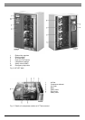
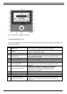
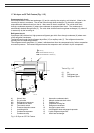
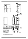
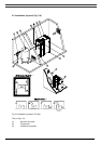
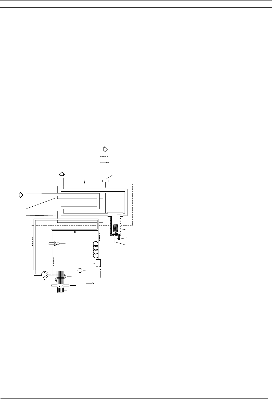
1.7 Air dryer on SF Full-Feature (Fig. 1.15)
Compressed air circuit
Wet compressed air enters heat exchanger (13) and is cooled by the outgoing, cold, dried air. Water in the
incoming air starts to condense. The air then flows through heat exchanger (11) where the refrigerant
evaporates and withdraws heat from the air. More water in the air condenses. The cold air then flows
through condensate separator (3) where the condensate is separated from the air. The condensate is
automatically drained through outlet (5). The cold, dried air then flows through heat exchanger (13), where it
is warmed up by the incoming air.
Refrigerant circuit
Compressor (M1) delivers hot, high-pressure refrigerant gas which flows through condenser (9) where most
of the refrigerant condenses.
The liquid flows through liquid refrigerant dryer/filter (12) to capillary tube (7). The refrigerant leaves the
capillary tube at evaporating pressure.
The refrigerant enters evaporator (11) where it withdraws heat from the compressed air by further evaporation
at constant pressure. The heated refrigerant leaves the evaporator and is sucked in by the compressor.
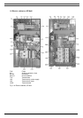
AO
AI
5
6
4
3
2
1
13
11
12
REFRIGERANT LIQUID (3)
REFRIGERANT GAS (2)
AIR (1)
50972D
7
10
S3
9
8
M2
M1
Text on Fig. 1.15
(1) Air
(2) Refrigerant gas
(3) Refrigerant liquid
AI Wet air inlet 5 Automatic condensate drain
AO Dry air outlet 6 Manual condensate drain valve
M1 Refrigerant compressor 7 Capillary tube
M2 Condenser fan motor 8 Condenser cooling fan
S3 Fan control switch 9 Refrigerant condenser
1 Pressure dewpoint sensor 10 Hot gas by-pass valve
2 Insulating block 11 Air/refrigerant heat exchanger/evaporator
3 Condensate separator 12 Liquid refrigerant dryer/filter
4 Condensate trap 13 Air/air heat exchanger
Fig. 1.15 Dryer on SF Full-Feature