


Instruction book
2920 1521 00 23
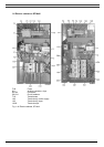
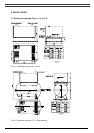
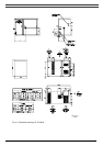
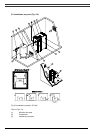
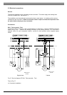
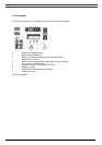
1 Install the compressor on a level floor, in a cool but frost-free room which is well-ventilated.
The air should be clean.
2 Position of compressed air outlet valve.
3 The maximum total pipe length can be calculated as follows:
L = (dP x d
5
x P) / (450 x Qc
1.85
)
L = pipe length in m
dP = maximum allowable pressure drop (recommended 0.1 bar)
d = inner diameter of pipe in mm
P = compressor outlet pressure in bar absolute
Qc = free air delivery of compressor in l/s
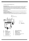
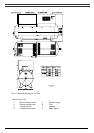
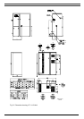
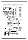
4/13 Ventilation: the inlet grids and fan for compressor room ventilation should be installed in
such a way that any recirculation of cooling air to the compressor or dryer is avoided. The
air velocity to the grids must be limited to 5 m/s. The maximum allowable pressure drop
over the cooling air ducts is 50 Pa. If this pressure drop is exceeded, a fan is needed at the
outlet of the cooling air ducts. The maximum air temperature at the compressor intake
opening is 40 °C.
For alternatives 1 and 3, the required ventilation capacity to limit the compressor room
temperature can be calculated as follows:
Qv = 0.92 N/dT
Qv = required ventilation capacity in m³/s
N = shaft input of compressor in kW
dT= temperature increase in compressor room in °C
For alternatives 2 and 4, the fan capacity should match the compressor fan capacity at a
pressure head equal to the pressure drop caused by the outlet cooling air ducts.
5 Position of control cubicle with monitoring panel.
6 Position of main cable entry. See section 7.1 for the recommended electric cables. See
section 2.3 for connecting the power supply.
7 Optional filters can be installed in the pressure line downstream of the air outlet valve, e.g.:
A DD filter for general-purpose filtration. The filter traps solid particles down to 1 micron. A
PD filter for filtration down to 0.01 micron. A PD filter must be installed downstream of a DD
filter. If odours are undesirable, a filter of the QD type should be installed downstream of the
PD filter. It is recommended to install by-pass pipes to isolate the filters during servicing.
8 Safety valve.
9 Position of the drain flexibles. The flexibles towards the drain collector must not dip into the
water of the drain collector.
10 Cooling air outlet, compressor elements.
11 Bodywork ventilation outlet.
12 Cooling air outlet, air cooler and dryer.
14 Data plate