


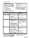
TYPE
OF
PROBLEM
MOTOR
WON7
OPERATE
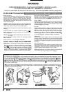
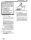
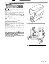
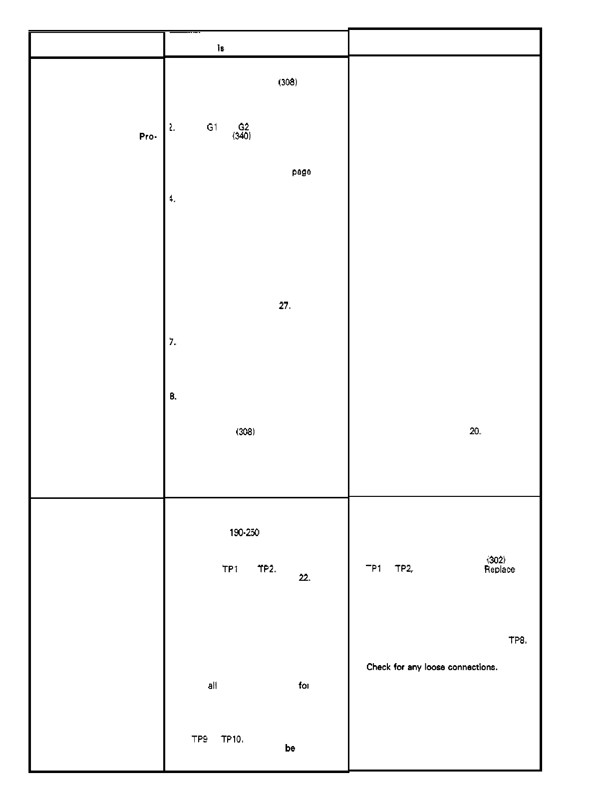
Diagnosing circuit board
in
-
dicator lamps. The normal
condition is red lamp on,
clear lamp
on
when board
is
telling
pump
to
run.
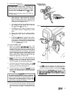
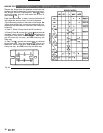
cedure
Warning. Remove
Follow
Pressure Relief
Pro-
gun from hose. Remove
pressure control cover and
check for faulty condition of
circuit board lamps.
Condition A both lamps on;
pump won't operate and
motor is not running
Condition B
Both lamps
off
~~~~~~
WHAT TO CHECK
If
check
Is
OK,
go
to
next check
I.
Check leads from bridge 1308) to motor
to be sure they are securely fastened
and properly mated.
1.
Check G1 and G2 connections between
circuit board
(3401
and bridge
1308)
for
damage or loose terminals.
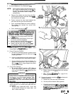
3.
Check for loose motor brush lead con
-
nections and terminals. See page 27.
4.
Check brush length which should be 14
mm minimum.
See
page 27.
at the same rate on both sides of the
NOTE also
that
the brushes do not wear
motor.
5.
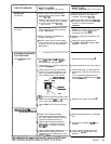
Check for broken or misaligned motor
brush springs. Rolled portion of spring
must rest squarely on top of brush. See
page
27.
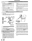
6.
Check motor brus'hes for binding
in
brush holders. See page
27.
7.
Check motor armature commutator for
burn spots, gouges and axtreme
rouohness. Remove motor cover and
brush inspection plates to check.
See
page
27.
6.
Check motor armature for shorts using
armature tester (growler) or perform spin
test.
See
page 15.
9.
Check bridge
1308)
by substituting with
a good bridge or performing bridge test.
See
page 16.
CAUTION: D
O
not perform this check
until
armature is determined to be good.
A bad armature will immediately burn
out
a
good bridge.
1. Check electrical supply. Connect
voltmeter to electrical outlet. Meter
should read
190.250 Volts.
2.
Check power supply to circuit board
with sprayer turned ON. Measure
voltage at
TPl and TP2. Meter should
read 190
-
250
Volts.
See page
7.2.
3.
Check a11 terminals and wires fog
damage or loose fit.
4.
Check motor thermal cutout switch.
Unplug sprayer. Allow motor to cool.
at
TP9 to TPlO. Use ohmmeter to check
Disconnect motor thermal switch leads
continuity. Switch should
be closed
when motor is cool.
WHAT TO DO
If
check is
NOT
OK
refer to this column
1.
Replace any loose terminals and crimp
to leads. Be sure male terminal blades
are straight and firmly connected to
mating part.
2.
Clean circuit board male terminals.
Replace loose or damaged terminals.
Securely reconnect leads.
3.
Tighten terminal screws. Replace
brushes if leads are damaged.
See page 27.
4.
Replace brushes. See page 27.
5. Replace spring
if
broken. Realign spring
with brush. See page
27.
6.
Clean brush holders. Remove carbon
with small cleaning brush. Align brush
free vertical brush movement.
lead with slot in brush holder to assure
7. Remove motor and have motor shop
resurface commutator if possible. See
page 27.
8.
Replace motor. See page
29.
9.
Replace bridge. See page
20.
1. Reset circuit breaker or replace outlet
fuse.
If
circuit breaker or fuse continues
to
open, see
"
Electrical Short
"
, page 14.
2. Unplug sprayer. Check continuity of
TPl to TPZ, and TP2 to TP3.
Replace
both poles of ONlOFF switch
(302) from
switch
if
faulty.
Check continuity of
RFI
filter (3101 from
TP4 to TP6 and TP3 to TP5. Replace
filter if faulty.
tinuity
from TP5 to TP7 and TP6 to
TP8.
Check
power supply cord (3111 for
con
-
Replace cord if faulty.
3. Replace damaged terminals and recon
-
nect securely.
4.
Replace electric motor
if
switch does not
close when motor is cool. See page
29.
10
307
-
671