


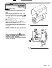
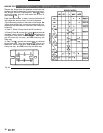
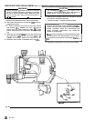
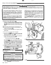
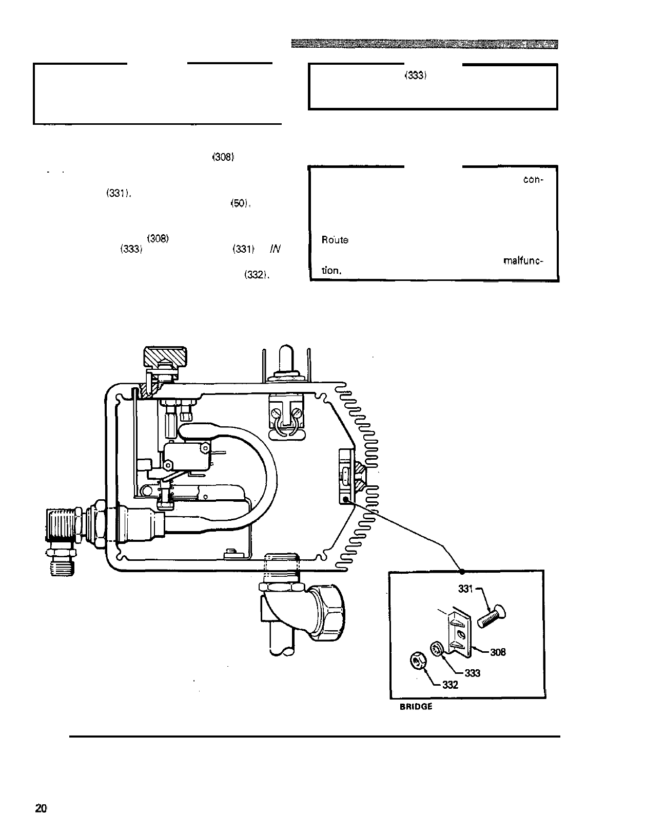
BRIDGE RECTIFIER REPLACEMENT
(See
Fig 161
WARNING
Before doing this procedure, follow the Pressure
the risk of a fluid injection injury, splashing
in
the
Relief Procedure Warning on page 17 to reduce
eyes or on the skin, injury from moving parts or
electric shock.
1
~ ~~~ ~~ ~~
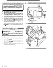
1.
Remove the pressure control cover and screws.
2.
Disconnect all wires from the bridge
(3081
at the ap
-
propriate terminals.
.
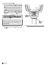
CAUTION
The lockwashers
(333)
must be in front
of
the
bridge to avoid overheating which
will
result
in
bridge failure. Refer to the Detail
in
Fig 16.
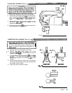
6. Make sure the bridge is flush with the side of the box
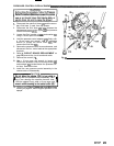
7. Connect all wires. Carefully route the wires.
I-
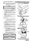
CAUTION
and tighten the screws securely.
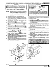
3. Outside the pressure control box on the right side are
Be sure the flat blade of the insulated male
con-
two
screws
(331).
Loosen,
but don't remove the
nector is centered in the wrap
-
around blade of the
screw near the back mounting plate
(50).
Then
female connector when the connections are
loosen and remove the front screw. Slide the bridge
made. Improper connections may cause the
out.
~~
sprayer to malfunction.
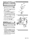
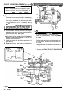
4.
Slide the new bridge
(308)
into the box being sure
the lockwasher
(333)
on the rear screw (331) is
/N
Ro'ute all wires carefully to avoid interference with
FRONT
of the bridge. Refer to the Detail in Fig 16.
the movement of the bourdon tube, circuit board,
or control box cover which could cause a
malfunc-
5.
Install the front screw, lockwasher and
nut
(332).
8.
Reinstall the pressure control cover and screws.
BRIDCE
INSTALLATION
DETAIL
Fig
16
20
307
-
671