


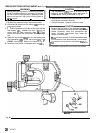
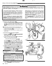
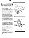
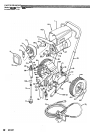

MOTOR CAPACITOR REPLACEMENT
(See
Figs
29
&
30)
WARNING
the risk of
a
fluid injection injury, splashing in the
Relief Procedure Warning on page 17 to reduce
eyes or on the skin, injury from moving parts or
1. Remove the control box cover
(48).
Disconnect the
motor leads.
2.
Remove the fan cover IF) and screws
(G)
from the
rear of the motor.
See
Fig
29.
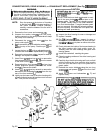
3.
Use
a
screwdriver to
gently
lift the fan tab out of the
motor shaft groove and remove the fan
(El.
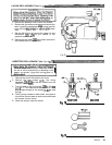
4.
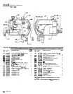
Remove the inspection cover
(J),
screws
(H),
and
gasket
(K)
from each side
of
the motor
(2).
See
Fig
29.
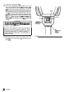
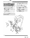
5.
Push down slightly on the spring clip and pull the
clip out of the brush holder. See Fig
30.
6. Gently push the brushes out of the brush holder
and inspect. Replace if necessary.
See
page 27.
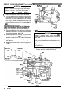
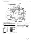
7. Make
a
matchmark between the front end
bell
(L)
and the motor housing and the rear end bell (M)
and the motor housing to use as alignment marks
of the motor housing. Refer to Fig
29.
during reassembly.
Also
make
a
mark on the
front
8.
Use
a
11
mm (7/16) socket wrench to remove the
nuts from the rear end bell
(MI.
9.
Gently
tap
alternate ears of the rear end bell with
a
plastic mallet to loosen
it,
then
pull
it
straight
off.
Do
not
pull the motor armature out.
Retain any
washers that fall
out
when the bell is
removed.
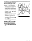
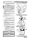
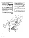
10.
To
replace
the
capacitor, remove the brush lead ter-
minal screws
(Y)
and the screw
(Z)
going into the
insulation plate of the rear end bell. Install
a
new
capacitor
(X),
making sure the ceramic case
of
the
capacitor
is
not cracked. Maintain
a
3
mm
(1/8")
clearance'between the capacitor and any grounded
same time.
metal parts. Always replace both capacitors at the
11. Position the rear end
bell
(MI over the
tie
bolts and
push
it
onto the motor housing. Align the metch-
nuts.
marks carefully and install the lockwashers and
12. Position the
fan
(E)
over the motor shaft and push
it
motor shaft groove.
into place, making sure the fan
tabs
engage
in
the
13.
Install the fan cover and screws.
14.
Reconnect the motor leads in the pressure control
box and reinstall the conduit
(41).Push conduit seal
(105)
into conduit elbow, around the motor lead.
Reinstall the pressure control cover
(48)
and screws
(51).
Fig
29
1
I
HOLDER
BRUSH
'4
Ll
SHOWN WITH MOTOR LEAD
DETAIL
OF
MOTOR
BRUSH
FACING BACK
OF
MOTOR
Fig
30
28
307-671