


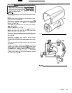
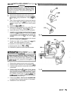
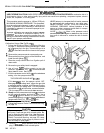
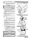
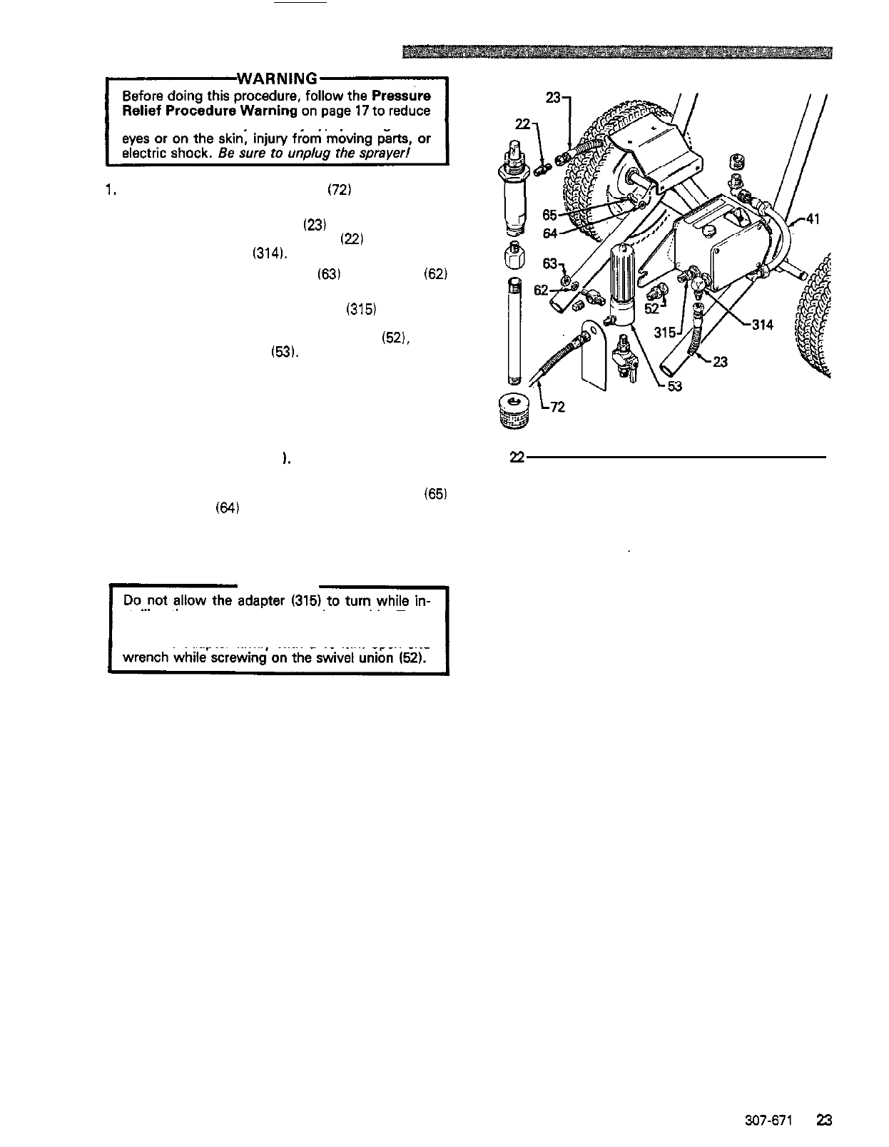
PRESSURE CONTROL REPLACEMENT
the risk of a fluid injection injury, splashing in the
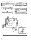
1. Disconnect the main fluid hose (72) and the secon
-
dary fluid hose, if used, from the sprayer.
2. Disconnect the fluid hose
(23)
from between the
displacement pump outlet nipple
(22)
and pressure
control inlet elbow
(314).
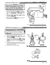
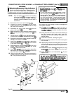
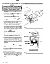
3.
Loosen the filter bracket nut
(63)
and washer
(62)
using a 19
mm
open end wrench.
4.
Hold the pressure control adapter (315) firmly with
wrench to loosen the swivel union
(52).
then
a
19
mm
open end wrench.
Use
an adjustable
remove the fluid filter
(53).
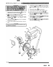
5. Remove the pressure control cover and screws, and
terminals.
disconnect the four motor leads at the appropriate
6. Refer
to
CIRCUIT BOARD REPLACEMENT
on
page
22,
remove the circuit board and retain.
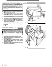
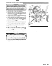
7.
Remove the conduit (41
1.
Fig
22
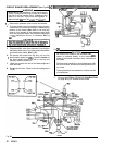
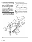
8.
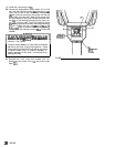
Use
a
13 mm open end wrench to loosen and
remove the pressure control mounting screws 165)
and washers
(64)
located below the pressure con
-
trol box. Remove the box.
9. Install the new pressure control assembly
in
the
reverse order of disassembly.
CAUTION
stalling the new pressure control assembly. Turn
-
ing
it
can damage the sensitive bourdon tube.
Hold the adapter firmly
with
a 19 mm open end
10.
Perform the
STALL PRESSURE CALIBRATION
starting on page 24, before regular operation of the
sprayer.
307-671
23